Theft Deterrent System -- Terminals Of Ecu |
| CHECK THEFT WARNING ECU |

Disconnect the T16 ECU connector.
Measure the voltage and resistance of the wire harness side connector.
Symbols (Terminal No.) Wiring Color Terminal Description Condition Specified Condition IG (T16-4) - E (T16-1) R-L - W-B Ignition power supply Ignition switch OFF Below 1 V IG (T16-4) - E (T16-1) R-L - W-B Ignition power supply Ignition switch ON 10 to 14 V +B1 (T16-3) - E (T16-1) L-Y - W-B +B (ECU-B) power source Always 10 to 14 V +B2 (T16-12) - E (T16-1) LG - W-B +B (DOOR) power source Always 10 to 14 V DSWH (T16-9) - E (T16-1) G-R - W-B Security courtesy switch input Engine hood fully closed 10 kΩ or higher DSWH (T16-9) - E (T16-1) G-R - W-B Security courtesy switch input Engine hood open Below 1 Ω E (T16-1) - Body ground W-B - Body ground Ground Always Below 1 Ω L2 (T16-20) - Body ground L - Body ground Door control switch (master switch) lock output Door control switch (master switch) LOCK Below 1 Ω L2 (T16-20) - Body ground L - Body ground Door control switch (master switch) lock output Door control switch (master switch) OFF 10 kΩ or higher UL3 (T16-21) - Body ground L-W - Body ground Door control switch (master switch) unlock output Door control switch (master switch) UNLOCK Below 1 Ω UL3 (T16-21) - Body ground L-W - Body ground Door control switch (master switch) unlock output Door control switch (master switch) OFF 10 kΩ or higher KSW (T16-5) - Body ground G-Y - Body ground Unlock warning switch No key in ignition key cylinder 10 kΩ or higher KSW (T16-5) - Body ground G-Y - Body ground Unlock warning switch Key inserted in ignition key cylinder Below 1 Ω - If the result is not as specified, there may be a malfunction on the wire harness side.
- If the result is not as specified, there may be a malfunction on the wire harness side.
Reconnect the T16 ECU connector.
Measure the voltage of the connector.
Symbols (Terminal No.) Wiring Color Terminal Description Condition Specified Condition IND (T16-22) - E (T16-1) G-R - W-B Security indicator light signal output Security indicator light is flashing
(theft deterrent system is operating)Alternating between
below 1 V and 10 to 14 VCTY (T16-7) - E (T16-1) R-L - W-B All courtesy switch signals input Driver side, front passenger side, rear RH or rear LH door closed 10 to 14 V CTY (T16-7) - E (T16-1) R-L - W-B All courtesy switch signals input Driver side, front passenger side, rear RH or rear LH door open Below 1 V HORN (T16-24) - E (T16-1) W-R - W-B Both vehicle horn signals output
(low pitched and high pitched)Armed state 10 to 14 V HORN (T16-24) - E (T16-1) W-R - W-B Vehicle horn signal output Alarm sounding state Below 1 V SH- (T16-26) - E (T16-1) B - W-B Security horn signal output Security horn is sounding
(theft deterrent system is in alarm sounding state)Alternating between below 1 V and 10 to 14 V HAZD (T16-23) - E (T16-1) G-O - W-B All hazard warning light signals output Hazard warning lights are flashing
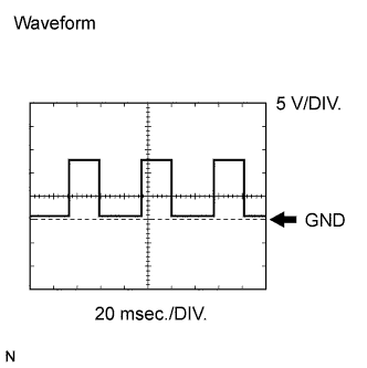
(theft deterrent system is in alarm sounding state)Alternating between below 1 V and 10 to 14 V SPD (T16-15) - E (T16-1) V-R - W-B Speed signal from combination meter Ignition switch ON, one driving wheel is rotating slowly Pulse generation
(see waveform)- If the result is not as specified, the ECU may have a malfunction.
- If the result is not as specified, the ECU may have a malfunction.
Using an oscilloscope, check the waveform.
Waveform (Reference) Item Content Symbols (Terminal No.) SPD (T16-15) - E (T16-1) Tool Setting 5 V/DIV., 20 msec./DIV. Condition While driving vehicle - HINT:
- The wavelength becomes shorter as the vehicle speed increases.
 |
| CHECK INSTRUMENT PANEL JUNCTION BLOCK (INTEGRATION RELAY) |
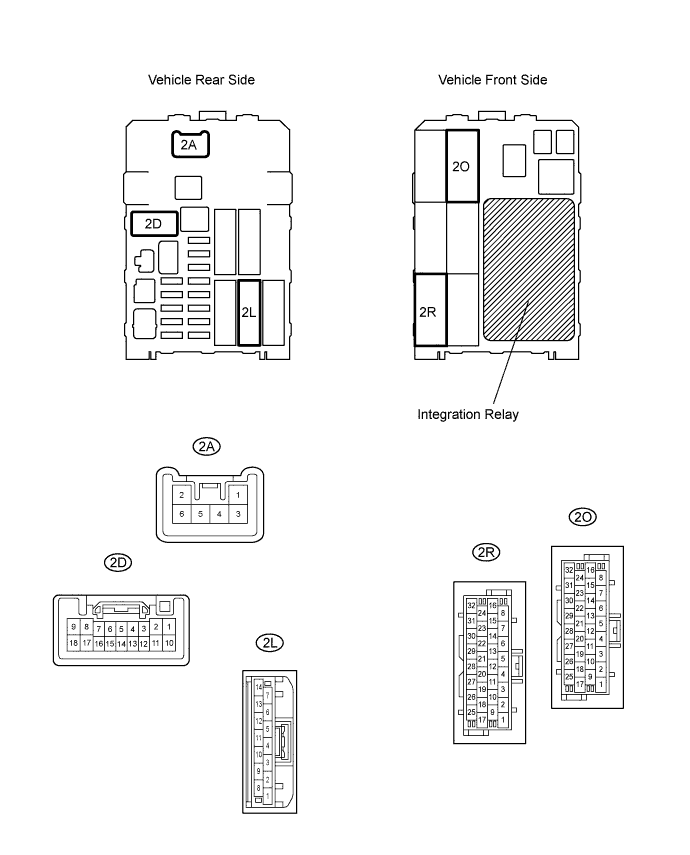
Disconnect the 2A, 2D and 2L junction block connectors.
Measure the voltage and resistance of the wire harness side connectors.
Symbols (Terminal No.) Wiring Color Terminal Description Condition Specified Condition BECU (2L-12) - GND (2D-9) L - W-B +B (BECU) power source Always 10 to 14 V GND (2D-9, 18) - Body ground W-B - Body ground Ground Always Below 1 Ω L1 (2A-4) - Body ground L - Body ground Door control switch (master switch) lock input Door control switch (master switch) LOCK 10 kΩ or higher L1 (2A-4) - Body ground L - Body ground Door control switch (master switch) lock input Door control switch (master switch) OFF Below 1 Ω UL1 (2D-4) - Body ground L-W - Body ground Door control switch (master switch) unlock input Door control switch (master switch) UNLOCK 10 kΩ or higher UL1 (2D-4) - Body ground L-W - Body ground Door control switch (master switch) unlock input Door control switch (master switch) OFF Below 1 Ω - If the result is not as specified, there may be a malfunction on the wire harness side.
- If the result is not as specified, there may be a malfunction on the wire harness side.
Reconnect the 2A, 2D and 2L junction block connectors.
Measure the voltage of the wire harness side connectors.
Symbols (Terminal No.) Wiring Color Terminal Description Condition Specified Condition ACT+ (2R-28) - Body ground L - Body ground Door lock motor LOCK drive output (driver side door) Door control switch (master switch) or driver side door key cylinder OFF Below 1 V ACT+ (2R-28) - Body ground L - Body ground Door lock motor LOCK drive output (driver side door) Door control switch (master switch) or driver side door key cylinder LOCK 10 to 14 V ACT- (2R-27) - Body ground L-Y - Body ground Door lock motor UNLOCK drive output (driver side door) Door control switch (master switch) or driver side door key cylinder OFF Below 1 V ACT- (2R-27) - Body ground L-Y - Body ground Door lock motor UNLOCK drive output (driver side door) Door control switch (master switch) or driver side door key cylinder UNLOCK 10 to 14 V DCTY (2O-27) - Body ground R-B - Body ground Driver side courtesy switch input Driver side door closed 10 to 14 V DCTY (2O-27) - Body ground R-B - Body ground Driver side courtesy switch input Driver side door open Below 1 V - If the result is not as specified, there may be a malfunction in the junction block (relay).
- If the result is not as specified, there may be a malfunction in the junction block (relay).