Power Window Control System (W/ Jam Protection Function) Rear Power Window Lh Manual Function Does Not Operate With Rear Power Window Switch Lh
DESCRIPTION
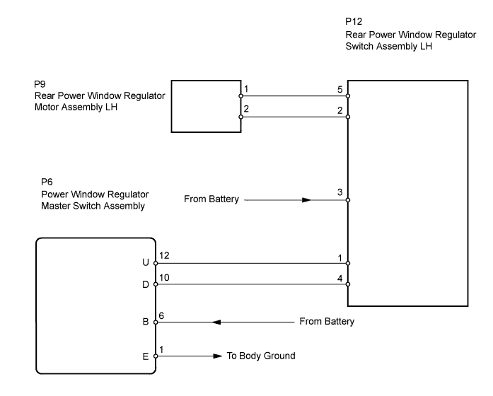
WIRING DIAGRAM
INSPECTION PROCEDURE
CHECK POWER WINDOW REGULATOR SWITCH ASSEMBLY (POWER SOURCE)
INSPECT POWER WINDOW REGULATOR SWITCH ASSEMBLY
CHECK WIRE HARNESS (SWITCH - MOTOR)
INSPECT POWER WINDOW REGULATOR MOTOR ASSEMBLY
CHECK WIRE HARNESS (MASTER SWITCH - REAR SWITCH LH)
POWER WINDOW CONTROL SYSTEM (w/ Jam Protection Function) - Rear Power Window LH Manual Function does not Operate with Rear Power Window Switch LH |
DESCRIPTION
If the rear LH side manual UP / DOWN function does not operate, a malfunction may be present in the power window regulator motor, power window regulator switch, power window regulator master switch or wire harness.
WIRING DIAGRAM
INSPECTION PROCEDURE
| 1.CHECK POWER WINDOW REGULATOR SWITCH ASSEMBLY (POWER SOURCE) |
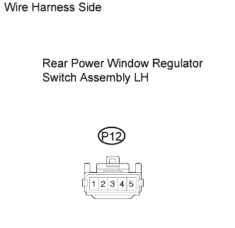
Disconnect the P12 regulator switch connector.
Measure the voltage of the wire harness side connector.
- Standard voltage:
Tester Connection
| Condition
| Specified Condition
|
P12-3 - Body ground
| Ignition switch ON
| 10 to 14 V
|
P12-3 - Body ground
| Ignition switch OFF
| Below 1 V
|
| | REPAIR OR REPLACE HARNESS AND CONNECTOR |
|
|
| 2.INSPECT POWER WINDOW REGULATOR SWITCH ASSEMBLY |
Remove the switch.
Measure the resistance of the switch when the switch is operated.
- Standard resistance:
Tester Connection
| Switch Condition
| Specified Condition
|
5 - 4
2 - 3
| UP
| Below 1 Ω
|
5 - 4
2 - 1
| OFF
| Below 1 Ω
|
5 - 3
2 - 1
| DOWN
| Below 1 Ω
|
| | REPLACE POWER WINDOW REGULATOR SWITCH ASSEMBLY |
|
|
| 3.CHECK WIRE HARNESS (SWITCH - MOTOR) |
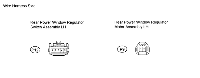
Disconnect the P12 switch connector.
Disconnect the P9 motor connector.
Measure the resistance of the wire harness side connectors.
- Standard resistance:
Tester Connection
| Specified Condition
|
P12-5 - P9-1
| Below 1 Ω
|
P12-2 - P9-2
| Below 1 Ω
|
P12-5 or P9-1 - Body ground
| 10 kΩ or higher
|
P12-2 or P9-2 - Body ground
| 10 kΩ or higher
|
| | REPAIR OR REPLACE HARNESS AND CONNECTOR |
|
|
| 4.INSPECT POWER WINDOW REGULATOR MOTOR ASSEMBLY |
Remove the motor.
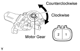
Apply battery voltage to connector terminals 1 and 2.
Check that the motor gear rotates smoothly as follows.
- OK:
Measurement Condition
| Specified Condition
|
Battery positive (+) → 1
Battery negative (-) → 2
| Motor gear rotates clockwise
|
Battery positive (+) → 2
Battery negative (-) → 1
| Motor gear rotates counterclockwise
|
| | REPLACE POWER WINDOW REGULATOR MOTOR ASSEMBLY |
|
|
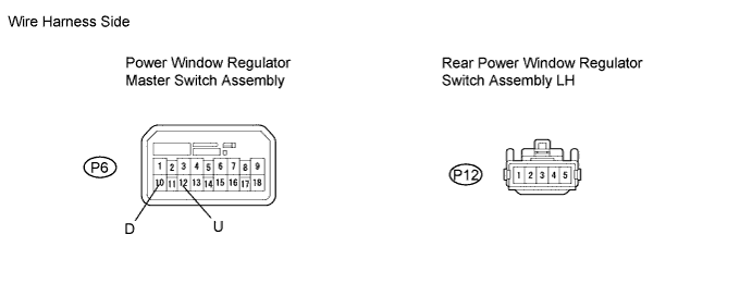
| 5.CHECK WIRE HARNESS (MASTER SWITCH - REAR SWITCH LH) |
Disconnect the P6 master switch connector.
Disconnect the P12 switch connector.
Measure the resistance of the wire harness side connectors.
- Standard resistance:
Tester Connection
| Specified Condition
|
P6-12 (U) - P12-1
| Below 1 Ω
|
P6-10 (D) - P12-4
| Below 1 Ω
|
P6-12 (U) or P12-1 - Body ground
| 10 kΩ or higher
|
P6-10 (D) or P12-4 - Body ground
| 10 kΩ or higher
|
| | REPAIR OR REPLACE HARNESS AND CONNECTOR |
|
|
| OK |
|
|
|
| REPLACE POWER WINDOW REGULATOR MASTER SWITCH ASSEMBLY |
|