Power Window Control System (W/ Jam Protection Function) Driver Side Power Window Manual Function Does Not Operate With Power Window Master Switch
DESCRIPTION
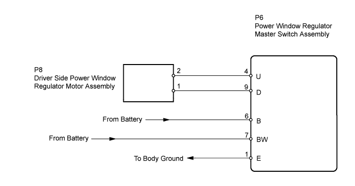
WIRING DIAGRAM
INSPECTION PROCEDURE
CHECK POWER WINDOW REGULATOR MASTER SWITCH ASSEMBLY (BW, B VOLTAGE)
CHECK POWER WINDOW REGULATOR MOTOR ASSEMBLY
INSPECT POWER WINDOW REGULATOR MASTER SWITCH ASSEMBLY (DRIVER SWITCH)
CHECK WIRE HARNESS (MASTER SWITCH - REGULATOR MOTOR)
POWER WINDOW CONTROL SYSTEM (w/ Jam Protection Function) - Driver Side Power Window Manual Function does not Operate with Power Window Master Switch |
DESCRIPTION
If the manual UP / DOWN function does not operate, a malfunction may be present in the power window regulator master switch, power window regulator motor or wire harness.
WIRING DIAGRAM
INSPECTION PROCEDURE
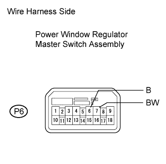
| 1.CHECK POWER WINDOW REGULATOR MASTER SWITCH ASSEMBLY (BW, B VOLTAGE) |
Disconnect the P6 master switch connector.
Measure the voltage of the wire harness side connector.
- Standard voltage:
Tester Connection
| Condition
| Specified Condition
|
P6-7 (BW) - Body ground
| Always
| 10 to 14 V
|
P6-6 (B) - Body ground
| Ignition switch ON
| 10 to 14 V
|
P6-6 (B) - Body ground
| Ignition switch OFF
| Below 1 V
|
| | REPAIR OR REPLACE HARNESS AND CONNECTOR (NO. 3 RELAY BLOCK - POWER WINDOW REGULATOR MASTER SWITCH) |
|
|
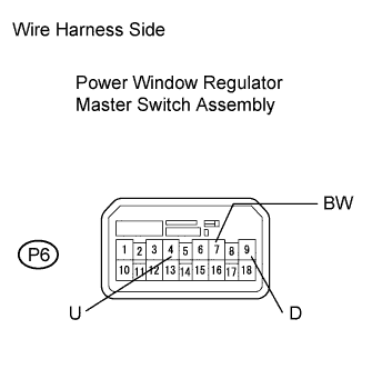
| 2.CHECK POWER WINDOW REGULATOR MOTOR ASSEMBLY |
Disconnect the P6 master switch connector.
Using a service wire, connect the terminals according to the table below.
Check operation of the power window regulator motor.
- OK:
Tester Connection
| Specified Condition
|
P6-4 (U) - P6-7 (BW)
P6-9 (D) - Body ground
| Power window moves UP
|
P6-4 (U) - Body ground
P6-7 (BW) - P6-9 (D)
| Power window moves DOWN
|
| | REPLACE POWER WINDOW REGULATOR MASTER SWITCH ASSEMBLY |
|
|
| 3.INSPECT POWER WINDOW REGULATOR MASTER SWITCH ASSEMBLY (DRIVER SWITCH) |
Remove the power window regulator master switch with its connectors still connected.
Measure the voltage of the power window regulator master switch connector.
- Standard voltage:
Tester Connection
| Switch Condition
| Specified Condition
|
4(U) - 1 (E)
| Ignition switch ON, driver side power window switch OFF → UP (manual operation)
| Below 1 V → 10 to 14 V
|
Ignition switch ON, driver side power window fully opened → driver side power window switch UP (AUTO operation) → driver side power window fully close
| Below 1 V → 10 to 14 V → Below 1 V
|
9 (D) - 1 (E)
| Ignition switch ON, driver side power window switch OFF → DOWN (manual operation)
| Below 1 V → 10 to 14 V
|
Ignition switch ON, driver side power window fully closed → driver side power window switch DOWN (AUTO operation) → driver side power window fully open
| Below 1 V → 10 to 14 V → Below 1 V
|
| | REPLACE POWER WINDOW REGULATOR MASTER SWITCH ASSEMBLY |
|
|
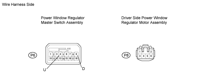
| 4.CHECK WIRE HARNESS (MASTER SWITCH - REGULATOR MOTOR) |
Disconnect the P6 master switch connector.
Disconnect the P7 motor connector.
Measure the resistance of the wire harness side connectors.
- Standard resistance:
Tester Connection
| Specified Condition
|
P6-9 (D) - P7-1
| Below 1 Ω
|
P6-4 (U) - P7-2
| Below 1 Ω
|
P6-9 (D) or P7-1 - Body ground
| 10 kΩ or higher
|
P6-4 (U) or P7-2 - Body ground
| 10 kΩ or higher
|
| | REPAIR OR REPLACE HARNESS AND CONNECTOR |
|
|
| OK |
|
|
|
| REPLACE POWER WINDOW REGULATOR MOTOR ASSEMBLY |
|