Air Conditioning System (For Automatic Air Conditioning System) Blower Motor Circuit
DESCRIPTION
WIRING DIAGRAM
INSPECTION PROCEDURE
ACTUATOR CHECK
CHECK HARNESS AND CONNECTOR (BLOWER MOTOR CONTROL - AIR CONDITIONING AMPLIFIER)
CHECK HARNESS AND CONNECTOR (BLOWER MOTOR CONTROL - BODY GROUND)
INSPECT BLOWER WITH FAN MOTOR SUB-ASSEMBLY
CHECK HARNESS AND CONNECTOR (BLOWER MOTOR CONTROL - BLOWER WITH FAN MOTOR AND DRIVER SIDE JUNCTION BLOCK)
CHECK AIR CONDITIONING AMPLIFIER ASSEMBLY
AIR CONDITIONING SYSTEM (for Automatic Air Conditioning System) - Blower Motor Circuit |
DESCRIPTION
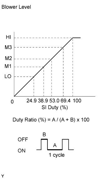 The blower motor is operated by signals from the air conditioning amplifier. Blower motor speed signals are determined by changes in the duty ratio*.The blower motor control controls the blower motor speed. The blower motor control reads the signal from the air conditioning amplifier and controls rotation and speed.
- HINT:
- *: The duty ratio is the ratio of the blower motor ON time (A) to the total of the blower motor ON and OFF time (A + B).
WIRING DIAGRAM
INSPECTION PROCEDURE
Enter actuator check mode (Toyota Fortuner RM000003PQ3001X.html).
Press the front DEF switch to change to the step operation (Toyota Fortuner RM000003PQ1001X.html).
Check the air flow level by hand.
Display Code
| Blower Level
|
0
| 0
|
1
| 1
|
2
| 16
|
3
| 16
|
4
| 16
|
5
| 16
|
6
| 16
|
7
| 16
|
8
| 16
|
9
| 31
|
- OK:
- Blower level changes in accordance with each display code.
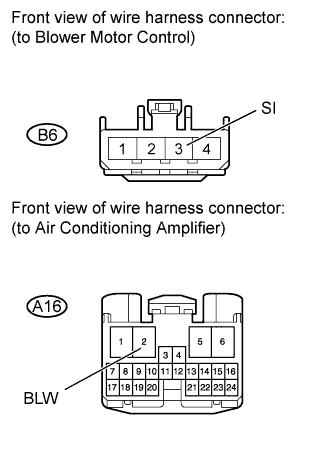
| 2.CHECK HARNESS AND CONNECTOR (BLOWER MOTOR CONTROL - AIR CONDITIONING AMPLIFIER) |
Disconnect the B6 control connector.
Disconnect the A16 amplifier connector.
Measure the resistance according to the value(s) in the table below.
- Standard Resistance:
Tester Connection
| Condition
| Specified Condition
|
B6-3 (SI) - A16-2 (BLW)
| Always
| Below 1 Ω
|
B6-3 (SI) - Body ground
| Always
| 10 kΩ or higher
|
| | REPAIR OR REPLACE HARNESS OR CONNECTOR |
|
|
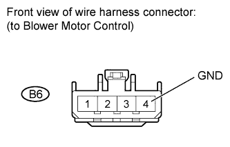
| 3.CHECK HARNESS AND CONNECTOR (BLOWER MOTOR CONTROL - BODY GROUND) |
Disconnect the B6 control connector.
Measure the resistance according to the value(s) in the table below.
- Standard Resistance:
Tester Connection
| Condition
| Specified Condition
|
B6-4 (GND) - Body ground
| Always
| Below 1 Ω
|
| | REPAIR OR REPLACE HARNESS OR CONNECTOR |
|
|
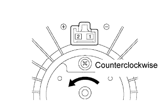
| 4.INSPECT BLOWER WITH FAN MOTOR SUB-ASSEMBLY |
Remove the motor.
Apply battery voltage to the motor and check that the motor rotates smoothly.
- OK:
Measurement Condition
| Specified Condition
|
Battery positive (+) → Terminal 2
Battery negative (-) → Terminal 1
| Motor rotates counterclockwise
|
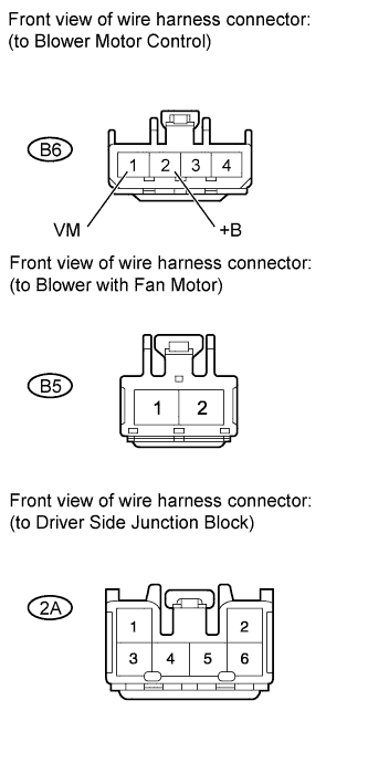
| 5.CHECK HARNESS AND CONNECTOR (BLOWER MOTOR CONTROL - BLOWER WITH FAN MOTOR AND DRIVER SIDE JUNCTION BLOCK) |
Disconnect the B6 control connector.
Disconnect the B5 motor connector.
Disconnect the 2A junction block connector.
Measure the resistance according to the value(s) in the table below.
- Standard Resistance:
Tester Connection
| Condition
| Specified Condition
|
B6-1 (VM) - B5-1
| Always
| Below 1 Ω
|
B6-2 (+B) - 2A-3
|
B5-2 - 2A-5
|
B6-2 (+B) - Body ground
| Always
| 10 kΩ or higher
|
B5-1 - Body ground
|
B5-2 - Body ground
|
| | REPAIR OR REPLACE HARNESS OR CONNECTOR |
|
|
| 6.CHECK AIR CONDITIONING AMPLIFIER ASSEMBLY |
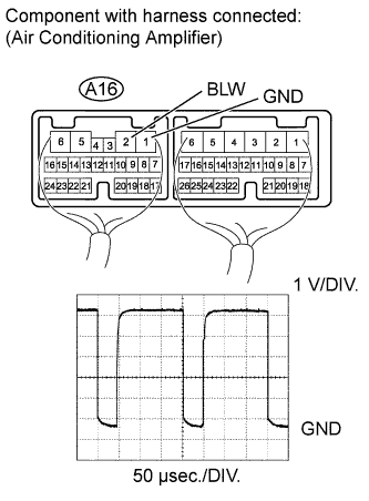
Remove the air conditioning amplifier with its connectors still connected.
Turn the ignition switch to ON.
Turn the blower switch ON (LO).
Using an oscilloscope, check the waveform of the amplifier.
Measurement ConditionItem
| Content
|
Tester Connection
| A16-2 (BLW) - A16-1 (GND)
|
Tool Setting
| 1 V/DIV., 50 μsec./DIV.
|
Condition
| Blower switch ON (LO)
|
- OK:
- Waveform is as shown in the illustration.
- HINT:
- Waveform varies depending on the blower switch setting.