Air Conditioning System (For Automatic Air Conditioning System) Heater Relay Circuit
DESCRIPTION
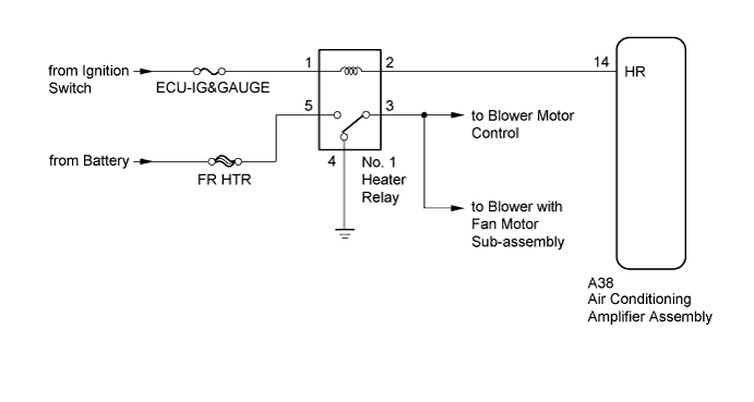
WIRING DIAGRAM
INSPECTION PROCEDURE
INSPECT NO. 1 HEATER RELAY
CHECK HARNESS AND CONNECTOR (NO. 1 HEATER RELAY - AIR CONDITIONING AMPLIFIER, BATTERY AND BODY GROUND)
CHECK AIR CONDITIONING AMPLIFIER ASSEMBLY
AIR CONDITIONING SYSTEM (for Automatic Air Conditioning System) - Heater Relay Circuit |
DESCRIPTION
The No. 1 heater relay is turned on by signals from the air conditioning amplifier assembly. The No. 1 heater relay supplies power to the blower motor control.
WIRING DIAGRAM
INSPECTION PROCEDURE
- NOTICE:
- Inspect the fuses for circuits related to this system before performing the following inspection procedure.
| 1.INSPECT NO. 1 HEATER RELAY |
Remove the No. 1 heater relay from the driver side junction block assembly.
Measure the resistance according to the value(s) in the table below.
- Standard Resistance:
Tester Connection
| Condition
| Specified Condition
|
3 - 4
| Battery voltage is not applied to terminals 1 and 2
| Below 1 Ω
|
3 - 5
| 10 kΩ or higher
|
3 - 4
| Battery voltage is applied to terminals 1 and 2
| 10 kΩ or higher
|
3 - 5
| Below 1 Ω
|
| | REPLACE NO. 1 HEATER RELAY |
|
|
| 2.CHECK HARNESS AND CONNECTOR (NO. 1 HEATER RELAY - AIR CONDITIONING AMPLIFIER, BATTERY AND BODY GROUND) |
Remove the No. 1 heater relay from the driver side junction block assembly.
Disconnect the A38 air conditioning amplifier assembly connector.
Measure the resistance according to the value(s) in the table below.
- Standard Resistance:
Tester Connection
| Condition
| Specified Condition
|
No. 1 heater relay terminal 2 - A38-14 (HR)
| Always
| Below 1 Ω
|
No. 1 heater relay terminal 2 - Body ground
| Always
| 10 kΩ or higher
|
No. 1 heater relay terminal 3 - Body ground
| Always
| 10 kΩ or higher
|
No. 1 heater relay terminal 4 - Body ground
| Always
| Below 1 Ω
|
Measure the voltage according to the value(s) in the table below.
- Standard Voltage:
Tester Connection
| Condition
| Specified Condition
|
No. 1 heater relay terminal 1 - Body ground
| Ignition switch ON
| 11 to 14 V
|
Ignition switch off
| Below 1 V
|
No. 1 heater relay terminal 5 - Body ground
| Always
| 11 to 14 V
|
| | REPAIR OR REPLACE HARNESS OR CONNECTOR |
|
|
| 3.CHECK AIR CONDITIONING AMPLIFIER ASSEMBLY |
Remove the air conditioning amplifier assembly with its connectors still connected (Toyota Fortuner RM000001K3A018X.html).
Measure the voltage according to the value(s) in the table below.
- Standard Voltage:
Tester Connection
| Switch Condition
| Specified Condition
|
A38-14 (HR) - Body ground
| - Ignition switch off
- Blower switch off
| Below 1 V
|
- Ignition switch ON
- Blower switch on (LO level)
| Below 1 V
|
- Ignition switch ON
- Blower switch off
| 11 to 14 V
|
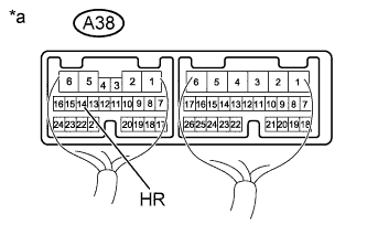
Text in Illustration*a
| Component with harness connected
(Air Conditioning Amplifier Assembly)
|