Air Conditioning System (For Automatic Air Conditioning System) Ig Power Source Circuit
DESCRIPTION
WIRING DIAGRAM
INSPECTION PROCEDURE
CHECK HARNESS AND CONNECTOR (AIR CONDITIONING AMPLIFIER - BATTERY AND BODY GROUND)
AIR CONDITIONING SYSTEM (for Automatic Air Conditioning System) - IG Power Source Circuit |
DESCRIPTION
This is the main power source supplied to the air conditioning amplifier when the ignition switch is ON. The power source supplied is used for operating components such as the air conditioning amplifier and servo motor.
WIRING DIAGRAM
INSPECTION PROCEDURE
- NOTICE:
- Inspect the fuses for circuits related to this system before performing the following inspection procedure.
| 1.CHECK HARNESS AND CONNECTOR (AIR CONDITIONING AMPLIFIER - BATTERY AND BODY GROUND) |
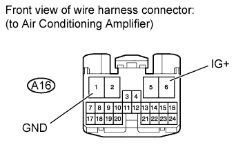
Disconnect the A16 amplifier connector.
Measure the voltage according to the value(s) in the table below.
- Standard Voltage:
Tester Connection
| Switch Condition
| Specified Condition
|
A16-6 (IG+) - Body ground
| Ignition switch ON
| 11 to 14 V
|
Measure the resistance according to the value(s) in the table below.
- Standard Resistance:
Tester Connection
| Condition
| Specified Condition
|
A16-1 (GND) - Body ground
| Always
| Below 1 Ω
|
| | REPAIR OR REPLACE HARNESS OR CONNECTOR |
|
|