Dtc 42 Air Inlet Damper Control Servo Motor Circuit
DESCRIPTION
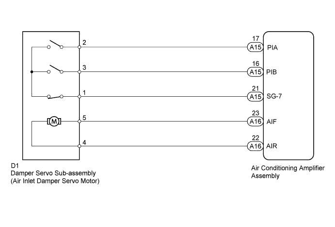
WIRING DIAGRAM
INSPECTION PROCEDURE
PERFORM ACTUATOR CHECK
CHECK HARNESS AND CONNECTOR (DAMPER SERVO - AIR CONDITIONING AMPLIFIER)
CHECK DAMPER SERVO SUB-ASSEMBLY (AIR INLET DAMPER SERVO MOTOR)
DTC 42 Air Inlet Damper Control Servo Motor Circuit |
DESCRIPTION
Recirculation of fresh air is controlled as follows:The damper servo (air inlet damper servo motor) sends the air inlet damper position as a pulse signal to the air conditioning amplifier. Then the air conditioning amplifier uses the pulse signal to determine how much the servo motor should be rotated forward/backward, and moves the air inlet damper to the appropriate position.- HINT:
- This DTC is also output if the damper and damper link are malfunctioning or unable to move properly. When this DTC is output, confirm that the mechanical parts of the damper and damper link are not defective or damaged.
DTC Code
| Detection Item
| Trouble Area
|
42
| Air inlet damper control servo motor activation request signal is output, but servo motor position data does not change or is inaccurate
| - Damper servo sub-assembly (Air inlet damper servo motor)
- Harness or connector
- Air conditioning amplifier assembly
|
WIRING DIAGRAM
INSPECTION PROCEDURE
Remove the glove box to visually check the damper servo (air inlet damper servo motor) operation.
Enter actuator check mode (Toyota Fortuner RM000003PQ3001X.html).
Press the DEF switch to change to the step operation (Toyota Fortuner RM000003PQ1001X.html).
Press the DEF switch to check the operation of the damper servo (air inlet damper servo motor).
Display Code
| Air Inlet Control Damper Position
|
0
| FRESH
|
1
| FRESH
|
2
| RECIRCULATION/FRESH
(50%)
|
3
| RECIRCULATION
|
4
| RECIRCULATION
|
5
| FRESH
|
6
| FRESH
|
7
| RECIRCULATION
|
8
| FRESH
|
9
| FRESH
|
- OK:
- Air inlet control damper position changes in accordance with each display code.
ResultResult
| Proceed to
|
OK (Checking from the PROBLEM SYMPTOMS TABLE)
| A
|
OK (Checking from the DTC)
| B
|
NG
| C
|
| 2.CHECK HARNESS AND CONNECTOR (DAMPER SERVO - AIR CONDITIONING AMPLIFIER) |
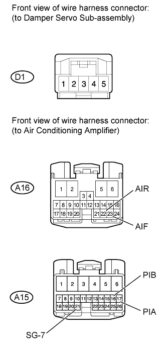
Disconnect the D1 servo connector.
Disconnect the A15 and A16 amplifier connectors.
Measure the resistance according to the value(s) in the table below.
- Standard Resistance:
Tester Connection
| Condition
| Specified Condition
|
D1-4 - A16-22 (AIR)
| Always
| Below 1 Ω
|
D1-5 - A16-23 (AIF)
|
D1-2 - A15-17 (PIA)
|
D1-3 - A15-16 (PIB)
|
D1-1 - A15-21 (SG-7)
|
D1-4 - Body ground
| Always
| 10 kΩ or higher
|
D1-5 - Body ground
|
D1-2 - Body ground
|
D1-3 - Body ground
|
D1-1 - Body ground
|
| | REPAIR OR REPLACE HARNESS OR CONNECTOR |
|
|
| 3.CHECK DAMPER SERVO SUB-ASSEMBLY (AIR INLET DAMPER SERVO MOTOR) |
Check if the malfunction disappears when a normally functioning damper servo (air inlet damper servo motor) is installed.
- OK:
- Air inlet control damper operates normally.