Dtc 23 Pressure Switch Circuit
DESCRIPTION
WIRING DIAGRAM
INSPECTION PROCEDURE
CHECK REFRIGERANT PRESSURE
CHECK AIR CONDITIONING OPERATION
CHECK HARNESS AND CONNECTOR (PRESSURE SWITCH - AIR CONDITIONING AMPLIFIER AND BODY GROUND)
DTC 23 Pressure Switch Circuit |
DESCRIPTION
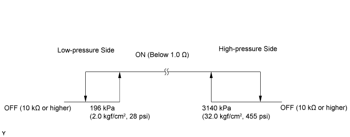
The pressure switch turns off when the A/C refrigerant pressure drops too low or rises too high. When the air conditioning amplifier detects the off state of the pressure switch, the amplifier outputs signals to the magnet clutch relay to turn the magnet clutch OFF.DTC Code
| Detection Item
| Trouble Area
|
23
| When either condition below is met:
- Open in pressure switch circuit
- Abnormal refrigerant pressure:
Below 196 kPa (2.0 kgf/cm2, 28 psi)
Over 3140 kPa (32.0 kgf/cm2, 455 psi)
| - Pressure switch
- Harness or connector
- Refrigerant pipe line
- Air conditioning amplifier assembly
|
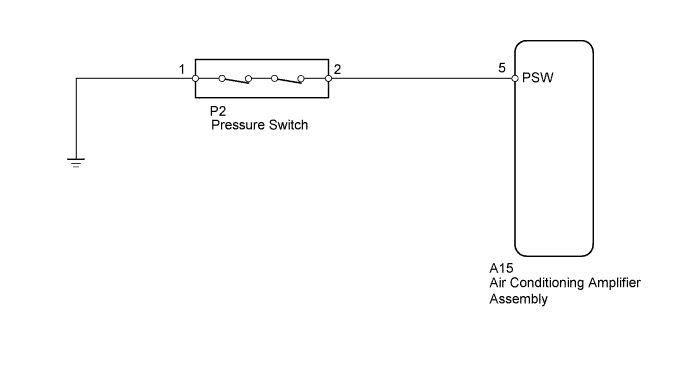
WIRING DIAGRAM
INSPECTION PROCEDURE
| 1.CHECK REFRIGERANT PRESSURE |
Install a manifold gauge.
Read the manifold gauge pressure when these conditions are met.
Test conditions:
- RECIRCULATION switch ON and temperature at air inlet is 30 to 35°C (86 to 95°F)
- Engine running at 1500 rpm
- Blower speed control switch in HI position
- Temperature control switch in COOL position
- Air conditioning switch ON
- Doors fully opened
- Standard pressure:
- Pressure on high-pressure side
- 1.37 to 1.57 MPa (13.9 to 16.0 kgf/cm2, 198 to 228 psi)
- HINT:
- If the refrigerant pressure is below 196 kPa (2.0 kgf/cm2, 28 psi), the refrigerant amount in the air conditioning cycle may have decreased significantly due to gas leakage or other problems.
| 2.CHECK AIR CONDITIONING OPERATION |
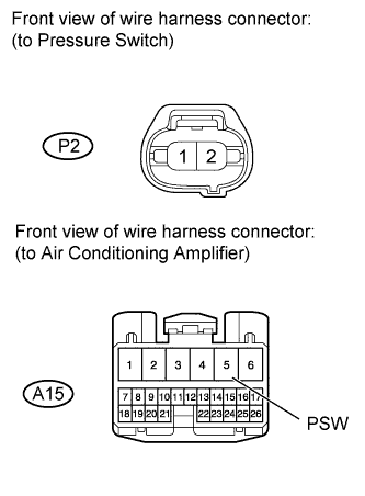
Disconnect the P2 switch connector.
Using a service wire, connect terminals 1 and 2 of the connector on the vehicle wire harness side.
Start the engine.
Turn the air conditioning switch ON and check the magnet clutch.
- OK:
- With terminals 1 and 2 connected, magnet clutch is ON.
- With terminals 1 and 2 disconnected, magnet clutch is OFF.
| 3.CHECK HARNESS AND CONNECTOR (PRESSURE SWITCH - AIR CONDITIONING AMPLIFIER AND BODY GROUND) |
Disconnect the P2 switch connector.
Disconnect the A15 amplifier connector.
Measure the resistance according to the value(s) in the table below.
- Standard Resistance:
Tester Connection
| Condition
| Specified Condition
|
A15-5 (PSW) - P2-2
| Always
| Below 1 Ω
|
P2-1 - Body ground
|
A15-5 (PSW) - Body ground
| Always
| 10 kΩ or higher
|
P2-2 - Body ground
|
ResultResult
| Proceed to
|
OK (Checking from the PROBLEM SYMPTOMS TABLE)
| A
|
OK (Checking from the DTC)
| B
|
NG
| C
|
| |
|
| | REPAIR OR REPLACE HARNESS OR CONNECTOR |
|
|