DESCRIPTION
WIRING DIAGRAM
INSPECTION PROCEDURE
When using intelligent tester:
CHECK CONNECTION OF VACUUM HOSE
CHECK VACUUM
PERFORM ACTIVE TEST USING INTELLIGENT TESTER (VACUUM SWITCHING VALVE FOR EGR CUT)
INSPECT VACUUM SWITCHING VALVE FOR EGR CUT
CHECK WIRE HARNESS (VACUUM SWITCHING VALVE FOR EGR CUT - ECM)
CHECK WIRE HARNESS (VACUUM SWITCHING VALVE FOR EGR CUT - INTEGRATION RELAY (MAIN RELAY))
CHECK ECM (EGR VOLTAGE)
CHECK OPERATION OF ELECTRIC VACUUM REGULATING VALVE FOR EGR
INSPECT ELECTRIC VACUUM REGULATING VALVE FOR EGR (RESISTANCE)
CHECK WIRE HARNESS (ELECTRIC VACUUM REGULATING VALVE FOR EGR - ECM)
CHECK WIRE HARNESS (ELECTRIC VACUUM REGULATING VALVE FOR EGR - INTEGRATION RELAY (MAIN RELAY))
INSPECT EGR VALVE ASSEMBLY
When not using intelligent tester:
CHECK CONNECTION OF VACUUM HOSE
CHECK VACUUM
INSPECT VACUUM SWITCHING VALVE FOR EGR CUT
INSPECT VACUUM SWITCHING VALVE FOR EGR CUT (OPERATION)
CHECK WIRE HARNESS (VACUUM SWITCHING VALVE FOR EGR CUT - ECM)
CHECK WIRE HARNESS (VACUUM SWITCHING VALVE FOR EGR CUT - INTEGRATION RELAY (MAIN RELAY))
CHECK ECM (EGR VOLTAGE)
INSPECT ELECTRIC VACUUM REGULATING VALVE FOR EGR (RESISTANCE)
INSPECT ELECTRIC VACUUM REGULATING VALVE FOR EGR (OPERATION)
CHECK WIRE HARNESS (ELECTRIC VACUUM REGULATING VALVE FOR EGR - ECM)
CHECK WIRE HARNESS (ELECTRIC VACUUM REGULATING VALVE FOR EGR - INTEGRATION RELAY (MAIN RELAY))
INSPECT EGR VALVE ASSEMBLY
ECD SYSTEM - EGR Control Circuit |
DESCRIPTION
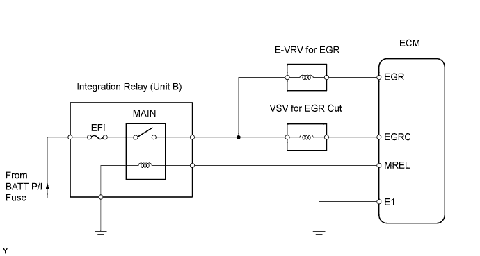
The EGR system recirculates exhaust gases, and is controlled to the proper volume to be suitable for all driving conditions. The recirculated gas mingles with the intake air, allowing the EGR system to slow down engine combustion and lower the combustion temperature. This helps reduce NOx emissions. In order to increase circulatory efficiency, the ECM adjusts the lift amount of the EGR valve and throttle valve. The VSV is turned ON by a signal from the ECM. This results in atmospheric air closing the EGR valve, which shuts off the exhaust gas (EGR cut-off).
WIRING DIAGRAM
INSPECTION PROCEDURE
- NOTICE:
- If the ECM is replaced, the new ECM needs initialization (Toyota Fortuner RM0000012X2005X.html).
When using intelligent tester:
| 1.CHECK CONNECTION OF VACUUM HOSE |
Check the connection of vacuum hose.
- OK:
- Vacuum hose is connected securely.
| | REPAIR OR REPLACE VACUUM HOSE |
|
|
Using a 3-way connector, connect a vacuum gauge to the vacuum hose between the E-VRV for EGR and EGR valve.
Warm up the engine to above 80°C (176°F).
Check the vacuum at 1,500 rpm.
- Result:
Vacuum
| Proceed to
|
0 kPa (0 mmHg, 0 in.Hg)
| A
|
0 kPa (0 mmHg, 0 in.Hg) to 28 kPa (210 mmHg, 8.3 in.Hg)
| B
|
Above 28 kPa (210 mmHg, 8.3 in.Hg)
| C
|
| 3.PERFORM ACTIVE TEST USING INTELLIGENT TESTER (VACUUM SWITCHING VALVE FOR EGR CUT) |
Disconnect the vacuum hose from the VSV.
Connect the intelligent tester to the DLC3.
Turn the ignition switch ON and turn the intelligent tester II ON.
Enter the following menus: Powertrain / Engine / Active Test / Activate the VSV for EGR Cut.
Check the operation.
- Result:
- When VSV is ON, air from port E flows out through air filter.
When VSV is OFF, air does not flow from port E to air filter.
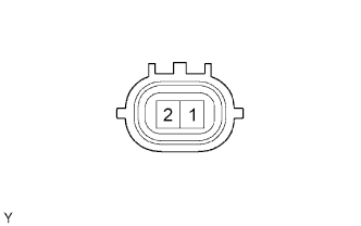
| 4.INSPECT VACUUM SWITCHING VALVE FOR EGR CUT |
Disconnect the V2 VSV connector.
Measure the resistance of the VSV.
- Standard resistance:
Tester Connection
| Condition
| Specified Condition
|
1 - 2
| 20°C (68°F)
| 37 to 44 Ω
|
| | REPLACE VACUUM SWITCHING VALVE FOR EGR CUT |
|
|
| 5.CHECK WIRE HARNESS (VACUUM SWITCHING VALVE FOR EGR CUT - ECM) |
Disconnect the V2 VSV connector.
Disconnect the E7 ECM connector.
Measure the resistance of the wire harness side connectors.
- Standard resistance:
Tester Connection
| Specified Condition
|
E6-18 (EGRC) - V2-2
| Below 1 Ω
|
E6-18 (EGRC) or V2-2 - Body ground
| 10 kΩ or higher
|
| | REPAIR OR REPLACE HARNESS AND CONNECTOR |
|
|
| 6.CHECK WIRE HARNESS (VACUUM SWITCHING VALVE FOR EGR CUT - INTEGRATION RELAY (MAIN RELAY)) |
Remove the integration relay from the engine room junction block (Toyota Fortuner RM0000014TJ00JX_01_0001.html).
Disconnect the 1J integration relay connector.
Disconnect the V2 VSV connector.
Measure the resistance of the wire harness side connectors.
- Standard resistance:
Tester Connection
| Specified Condition
|
1J-5 - V2-1
| Below 1 Ω
|
1J-5 or V2-1 - Body ground
| 10 kΩ or higher
|
| | REPAIR OR REPLACE HARNESS AND CONNECTOR |
|
|
| 7.CHECK ECM (EGR VOLTAGE) |
Disconnect the V1 E-VRV connector.
During idling, check the waveform of the ECM connector.
- OK:
Tester Connection
| Specified Condition
|
E6-9 (EGR) - E6-7 (E1)
| Correct waveform is as shown
|
Tool Setting
| Condition
|
5 V/DIV., 1 msec./DIV.
| Idling with warm engine
|
- HINT:
- The waveform varies depending on the E-VRV operation.
| 8.CHECK OPERATION OF ELECTRIC VACUUM REGULATING VALVE FOR EGR |
Disconnect the vacuum hoses from the E-VRV.
Connect the intelligent tester to the DLC3.
Turn the ignition switch ON and turn the intelligent tester ON.
Enter the following menus: Powertrain / Engine / Active Test / Control the EGR System.
Check the operation.
- OK:
- When E-VRV is ON, air from port E flows out through port F.
E-VRV is OFF, air does not flow from port E to port F.
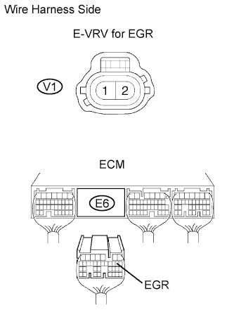
| 9.INSPECT ELECTRIC VACUUM REGULATING VALVE FOR EGR (RESISTANCE) |
Disconnect the V1 E-VRV connector.
Measure the resistance of the E-VRV.
- Standard resistance:
Tester Connection
| Condition
| Specified Condition
|
1 - 2
| 20°C (68°F)
| 11 to 13 Ω
|
| | REPLACE ELECTRIC VACUUM REGULATING VALVE FOR EGR |
|
|
| 10.CHECK WIRE HARNESS (ELECTRIC VACUUM REGULATING VALVE FOR EGR - ECM) |
Disconnect the V1 E-VRV connector.
Disconnect the E7 ECM connector.
Measure the resistance of the wire harness side connectors.
- Standard resistance:
Tester Connection
| Specified Condition
|
E6-9 (EGR) - V1-2
| Below 1 Ω
|
E6-9 (EGR) or V1-2 - Body ground
| 10 kΩ or higher
|
| | REPAIR OR REPLACE HARNESS AND CONNECTOR |
|
|
| 11.CHECK WIRE HARNESS (ELECTRIC VACUUM REGULATING VALVE FOR EGR - INTEGRATION RELAY (MAIN RELAY)) |
Remove the integration relay from the engine room junction block (Toyota Fortuner RM0000014TJ00JX_01_0001.html).
Disconnect the 1J integration relay connector.
Disconnect the V1 E-VRV connector.
Measure the resistance of the wire harness side connectors.
- Standard resistance:
Tester Connection
| Specified Condition
|
1J-5 - V1-1
| Below 1 Ω
|
1J-5 or V1-1 - Body ground
| 10 kΩ or higher
|
| | REPAIR OR REPLACE HARNESS AND CONNECTOR |
|
|
| 12.INSPECT EGR VALVE ASSEMBLY |
| | REPLACE EGR VALVE ASSEMBLY |
|
|
When not using intelligent tester:
| 1.CHECK CONNECTION OF VACUUM HOSE |
Check the connection of vacuum hose.
- OK:
- Vacuum hose is connected securely.
| | REPAIR OR REPLACE VACUUM HOSE |
|
|
Using a 3-way connector, connect a vacuum gauge to the vacuum hose between the E-VRV for EGR and EGR valve.
Warm up the engine to above 80°C (176°F).
Check the vacuum at 1,500 rpm.
- Result:
Vacuum
| Proceed to
|
0 kPa (0 mmHg, 0 in.Hg)
| A
|
0 kPa (0 mmHg, 0 in.Hg) to 28 kPa (210 mmHg, 8.3 in.Hg)
| B
|
Above 28 kPa (210 mmHg, 8.3 in.Hg)
| C
|
| 3.INSPECT VACUUM SWITCHING VALVE FOR EGR CUT |
Disconnect the V2 VSV connector.
Measure the resistance of the VSV.
- Standard resistance:
Tester Connection
| Condition
| Specified Condition
|
1 - 2
| 20°C (68°F)
| 37 to 44 Ω
|
| | REPLACE VACUUM SWITCHING VALVE FOR EGR CUT |
|
|
| 4.INSPECT VACUUM SWITCHING VALVE FOR EGR CUT (OPERATION) |
| | REPLACE VACUUM SWITCHING VALVE FOR EGR CUT |
|
|
| 5.CHECK WIRE HARNESS (VACUUM SWITCHING VALVE FOR EGR CUT - ECM) |
Disconnect the V2 VSV connector.
Disconnect the E7 ECM connector.
Measure the resistance of the wire harness side connectors.
- Standard resistance:
Tester Connection
| Specified Condition
|
E7-18 (EGRC) - V2-2
| Below 1 Ω
|
E7-18 (EGRC) or V2-2 - Body ground
| 10 kΩ or higher
|
| | REPAIR OR REPLACE HARNESS AND CONNECTOR |
|
|
| 6.CHECK WIRE HARNESS (VACUUM SWITCHING VALVE FOR EGR CUT - INTEGRATION RELAY (MAIN RELAY)) |
Remove the integration relay from the engine room junction block (Toyota Fortuner RM0000014TJ00JX.html).
Disconnect the 1J integration relay connector.
Disconnect the V2 VSV connector.
Measure the resistance of the wire harness side connectors.
- Standard resistance:
Tester Connection
| Specified Condition
|
1J-5 - V2-1
| Below 1 Ω
|
1J-5 or V2-1 - Body ground
| 10 kΩ or higher
|
| | REPAIR OR REPLACE HARNESS AND CONNECTOR |
|
|
| 7.CHECK ECM (EGR VOLTAGE) |
Disconnect the V1 E-VRV connector for EGR.
During idling, check the waveform of the ECM connector.
- Standard:
Tester Connection
| Specified Condition
|
E7-9 (EGR) - E7-7 (E1)
| Correct waveform is as shown
|
Tool Setting
| Condition
|
5 V/DIV., 1 msec./DIV.
| Idling with warm engine
|
- HINT:
- The waveform varies depending on the E-VRV operation for EGR.
| | REPAIR OR REPLACE HARNESS AND CONNECTOR |
|
|
| 8.INSPECT ELECTRIC VACUUM REGULATING VALVE FOR EGR (RESISTANCE) |
Disconnect the V1 E-VRV connector.
Measure the resistance of the E-VRV.
- Standard resistance:
Tester Connection
| Condition
| Specified Condition
|
1 - 2
| 20°C (68°F)
| 11 to 13 Ω
|
| | REPLACE ELECTRIC VACUUM REGULATING VALVE FOR EGR |
|
|
| 9.INSPECT ELECTRIC VACUUM REGULATING VALVE FOR EGR (OPERATION) |
| | REPLACE ELECTRIC VACUUM REGULATING VALVE FOR EGR |
|
|
| 10.CHECK WIRE HARNESS (ELECTRIC VACUUM REGULATING VALVE FOR EGR - ECM) |
Disconnect the V1 E-VRV connector.
Disconnect the E7 ECM connector.
Measure the resistance of the wire harness side connectors.
- Standard resistance:
Tester Connection
| Specified Condition
|
E7-9 (EGR) - V1-2
| Below 1 Ω
|
E7-9 (EGR) or V1-2 - Body ground
| 10 kΩ or higher
|
| | REPAIR OR REPLACE HARNESS AND CONNECTOR |
|
|
| 11.CHECK WIRE HARNESS (ELECTRIC VACUUM REGULATING VALVE FOR EGR - INTEGRATION RELAY (MAIN RELAY)) |
Remove the integration relay from the engine room junction block (Toyota Fortuner RM0000014TJ00JX.html).
Disconnect the 1J integration relay connector.
Disconnect the V1 E-VRV connector.
Measure the resistance of the wire harness side connectors.
- Standard resistance:
Tester Connection
| Specified Condition
|
1J-5 - V1-1
| Below 1 Ω
|
1J-5 or V1-1 - Body ground
| 10 kΩ or higher
|
| | REPAIR OR REPLACE HARNESS AND CONNECTOR |
|
|
| 12.INSPECT EGR VALVE ASSEMBLY |
| | REPLACE EGR VALVE ASSEMBLY |
|
|