FULLY TIGHTEN NO. 2 STEERING INTERMEDIATE SHAFT SUB-ASSEMBLY
INSTALL FRONT SIDE MEMBER TO FRONT SUSPENSION CROSSMEMBER BRACE
Steering Linkage -- Installation |
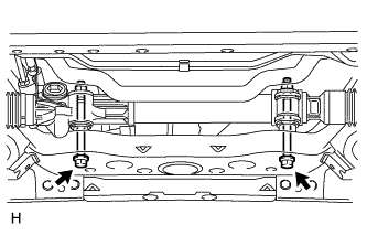
| 1. INSTALL POWER STEERING LINK ASSEMBLY |
Install the steering link with the 2 bolts and 2 nuts.
- Torque:
- 95 N*m{969 kgf*cm, 70 ft.*lbf}
- HINT:
- If necessary, return the differential to its original position and install the differential mount.
 |
| 2. INSTALL FRONT STABILIZER BAR FRONT |
Install the front stabilizer bar to the vehicle body.
| 3. STABILIZE SUSPENSION |
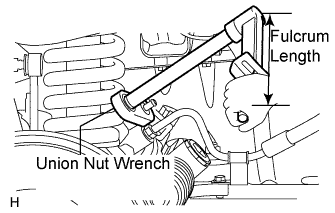
| 4. CONNECT STEERING GEAR OUTLET RETURN TUBE |
Using union nut wrench, connect the outlet return tube.
- Torque:
- 44 N*m{449 kgf*cm, 33 ft.*lbf}for use without union nut wrench
- 40 N*m{409 kgf*cm, 30 ft.*lbf}for use with union nut wrench
- HINT:
- Use a torque wrench with a fulcrum length of 300 mm (11.81 in.).
- This torque value is effective when union nut wrench is parallel to the torque wrench.
 |
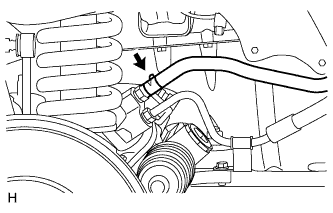
Install the hose with the clip.
 |
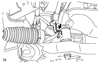
| 5. CONNECT PRESSURE FEED TUBE ASSEMBLY |
Install the pressure feed tube to the steering link with the bolt.
- Torque:
- 28 N*m{286 kgf*cm, 21 ft.*lbf}
 |
Using union nut wrench, tighten the flare nut and connect the pressure feed tube.
- Torque:
- 44 N*m{449 kgf*cm, 33 ft.*lbf}for use without union nut wrench
- 40 N*m{409 kgf*cm, 30 ft.*lbf}for use with union nut wrench
- HINT:
- Use a torque wrench with a fulcrum length of 300 mm (11.81 in.).
- This torque value is effective when union nut wrench is parallel to the torque wrench.
 |
| 6. FULLY TIGHTEN NO. 2 STEERING INTERMEDIATE SHAFT SUB-ASSEMBLY |
| 7. CONNECT TIE ROD END SUB-ASSEMBLY LH |
Connect the tie rod end to the steering knuckle arm with the nut.
- Torque:
- 91 N*m{928 kgf*cm, 67 ft.*lbf}
Install a new cotter pin.
| 8. CONNECT TIE ROD END SUB-ASSEMBLY RH |
- HINT:
- Use the same procedures described for the LH side.
| 9. INSTALL FRONT SIDE MEMBER TO FRONT SUSPENSION CROSSMEMBER BRACE |
Install the crossmember brace with the 8 bolts.
- Torque:
- 50 N*m{510 kgf*cm, 37 ft.*lbf}
| 10. INSTALL NO. 1 ENGINE UNDER COVER |
Install the under cover with the 4 bolts.
- Torque:
- 28 N*m{286 kgf*cm, 21 ft.*lbf}
| 11. INSTALL NO. 2 ENGINE UNDER COVER |
Install the under cover with the 4 bolts.
- Torque:
- 28 N*m{286 kgf*cm, 21 ft.*lbf}
| 12. INSTALL FRONT WHEEL |
| 13. PLACE FRONT WHEELS FACING STRAIGHT AHEAD |
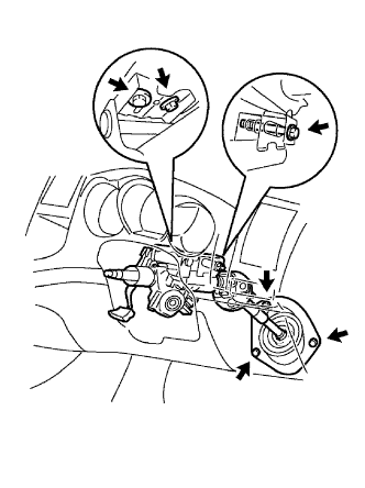
| 14. INSTALL WINDSHIELD WIPER SWITCH ASSEMBLY |
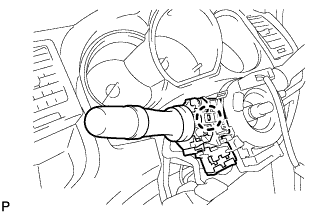 |
Attach the claw to install the wiper switch.
Connect the connectors.
- NOTICE:
- Do not push the claw with excessive force as damage may occur.
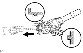
| 15. INSTALL HEADLIGHT DIMMER SWITCH ASSEMBLY |
Install the headlight dimmer switch with the claw as shown in the illustration.
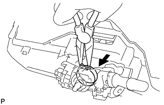
 |
Install the headlight dimmer switch with the clamp.
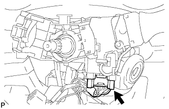
 |
Connect the connector.
 |
| 16. INSTALL SPIRAL CABLE SUB-ASSEMBLY |
| 17. INSTALL STEERING COLUMN COVER UPPER |
| 18. INSTALL STEERING COLUMN COVER LOWER |
Install the steering column with the 3 bolts.
- Torque:
- 21 N*m{214 kgf*cm, 15 ft.*lbf}
 |
Install the cover with the 3 bolts.
- Torque:
- 5.0 N*m{51 kgf*cm, 44 in.*lbf}
| 19. INSTALL STEERING WHEEL ASSEMBLY |
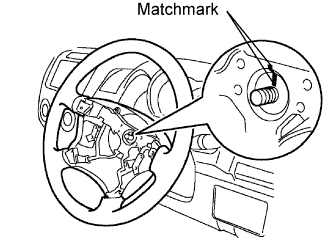 |
Align the matchmarks on the steering wheel and main shaft.
Install the steering set nut.
- Torque:
- 50 N*m{510 kgf*cm, 37 ft.*lbf}
| 20. INSPECT STEERING WHEEL CENTER POINT |
| 21. INSTALL STEERING PAD ASSEMBLY |
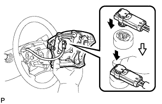 |
Support the steering pad with one hand as shown in the illustration.
Connect the airbag connector.
- NOTICE:
- When handling the airbag connector, do not damage the airbag wire harness.
Connect the horn connector.
Install the steering pad after confirming that the circumference grooves of the screws are caught on the screw case.
Using a T30 "torx" socket, install the 2 screws.
- Torque:
- 8.8 N*m{90 kgf*cm, 78 in.*lbf}
| 22. CONNECT CABLE TO NEGATIVE BATTERY TERMINAL |
| 23. INSPECT SRS WARNING LIGHT |
Check the SRS warning light (Toyota Fortuner RM000000YVX004X.html).
| 24. ADD POWER STEERING FLUID |
| 25. BLEED AIR FROM POWER STEERING SYSTEM |
Check the fluid level.
Jack up the front of the vehicle and support it with stands.
Turn the steering wheel.
With the engine stopped, turn the steering wheel slowly from lock to lock several times.
Lower the vehicle.
Start the engine. Run the engine at idle for a few minutes.
Turn the steering wheel.
With the engine idling, turn the steering wheel to the left or right full lock position and hold it there for 2 to 3 seconds. Then turn the steering wheel to the opposite full lock position and hold it there for 2 to 3 seconds.
Repeat the step above several times.
Stop the engine.
Check for foaming or emulsification. If the system has to be bled twice because of foaming or emulsification, check for fluid leaks in the system.
 |
Check the fluid level.
| 26. CHECK FOR POWER STEERING FLUID LEAKAGE |
| 27. INSPECT AND ADJUST FRONT WHEEL ALIGNMENT |
Inspect and adjust the front wheel alignment (Toyota Fortuner RM0000010MX004X.html).