PERFORM ACTIVE TEST USING INTELLIGENT TESTER (OPERATE VSV FOR ACIS)
INSPECT VSV FOR ACIS (OPERATION)
CHECK WIRE HARNESS (VSV FOR ACIS - ECM AND INTEGRATION RELAY [MAIN RELAY])
DTC P0660 Intake Manifold Tuning Valve Control Circuit / Open (Bank 1) |
DESCRIPTION
The Acoustic Control Induction System (ACIS) obtains high power torque in all engine speed ranges from low to high. This circuit is used to open and close the Intake Air Control Valve (IACV) in response to engine load and helps to increase the intake air efficiency inside the intake manifold. When the engine speed is between 2,200 and 4,100 rpm and the opening angle of the throttle valve is 60°or more, the ECM supplies current to the VSV to close the IACV (VSV is ON). For other situations, the IACV is usually open and the VSV is OFF.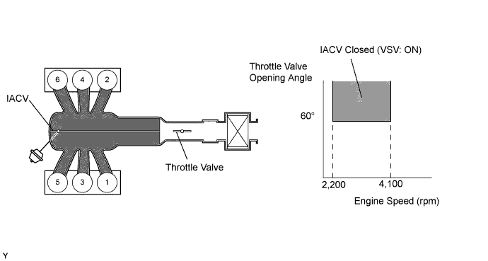
| DTC No. | DTC Detection Condition | Trouble Area |
| P0660 | Following conditions are met simultaneously for 0.5 sec. or more (2 trip detection logic) (a) Voltage of terminal ACIS of the ECM is low when VSV is OFF (b) Engine has started |
|
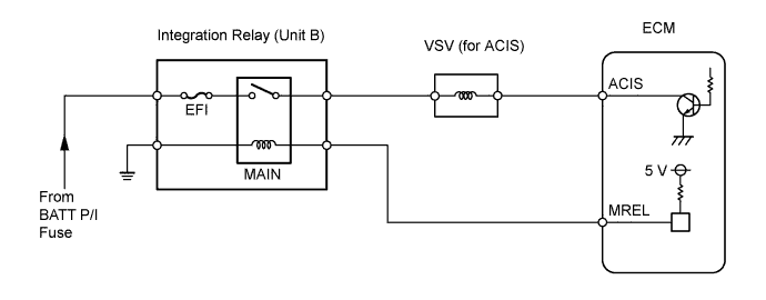
WIRING DIAGRAM
INSPECTION PROCEDURE
| 1.PERFORM ACTIVE TEST USING INTELLIGENT TESTER (OPERATE VSV FOR ACIS) |
 |
Disconnect the vacuum hose.
Connect the intelligent tester to the DLC3.
Start the engine and turn the tester ON.
Enter the following menus: Powertrain / Engine and ECT / Active Test / Activate the VSV for Intake Control.
Press the right of left button.
Check if the disconnected port sucks air when operating the ACIS VSV using the intelligent tester.
- OK:
Tester Operation Specified Condition VSV is ON Air from port E flows out through port F VSV is OFF Air from port E flows out through the air filter
|
| ||||
| NG | |
| 2.INSPECT VSV FOR ACIS (OPERATION) |
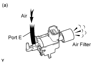  |
Check that air flows from port E to the air filter.
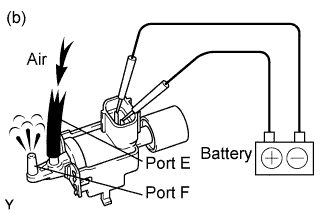
Apply battery positive voltage across the terminals.
Check that air flows from port E to port F.
|
| ||||
| OK | |
| 3.CHECK WIRE HARNESS (VSV FOR ACIS - ECM AND INTEGRATION RELAY [MAIN RELAY]) |
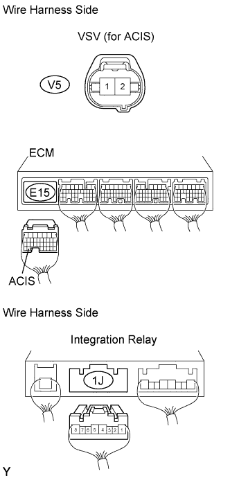 |
Check the wire harness between the VSV and ECM.
Disconnect the V5 VSV connector.
Disconnect the E15 ECM connector.
Measure the resistance of the wire harness side connectors.
- Standard resistance:
Tester Connection Specified Condition V5-2 (ACIS) - E15-33 (ACIS) Below 1 Ω V5-2 (ACIS) or E15-33 (ACIS) - Body ground 10 kΩ or higher
Check the wire harness between the VSV and integration relay.
Disconnect the V5 VSV connector.
Disconnect the 1J integration relay connector from engine room junction block (Toyota Fortuner RM0000014TJ00HX.html).
Measure the resistance of the wire harness side connectors.
- Standard resistance:
Tester Connection Specified Condition V5-1 (ACIS) - 1J-5 Below 1 Ω
|
| ||||
| OK | ||
| ||