Intake Air Control System System Diagram
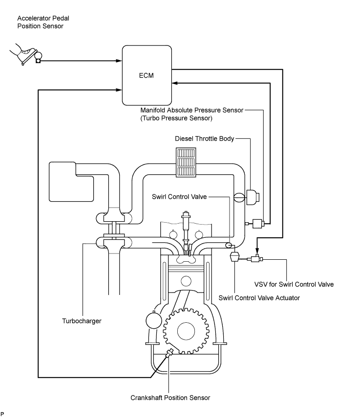
INTAKE AIR CONTROL SYSTEM ILLUSTRATION
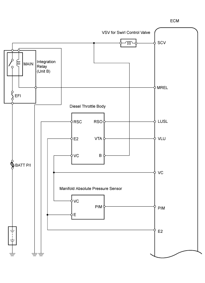
INTAKE AIR CONTROL SYSTEM WIRING DIAGRAM
INTAKE AIR CONTROL SYSTEM WIRING DIAGRAM
TURBOCHARGER SYSTEM ILLUSTRATION
TURBOCHARGER SYSTEM WIRING DIAGRAM
Intake Air Control System -- System Diagram |
| INTAKE AIR CONTROL SYSTEM ILLUSTRATION |
The swirl control valve is mounted on the intake manifold. The Vacuum Switching Valve (VSV) for swirl control valve changes the vacuum to actuate the actuator.First, the ECM determines the opening angle of the swirl control valve. Then it uses the VSV for swirl control valve to change the vacuum applied to the actuator's diaphragm to open and close the swirl control valve.
| INTAKE AIR CONTROL SYSTEM WIRING DIAGRAM |
| INTAKE AIR CONTROL SYSTEM WIRING DIAGRAM |
| TURBOCHARGER SYSTEM ILLUSTRATION |
- The turbocharger system is comprised of the Variable Nozzle (VN) type turbocharger, turbo motor driver and ECM.
- The turbocharger has a nozzle vane which opens and closes to control the volume of the exhaust gas flowing into the turbine. This, in turn, controls the boost pressure. When the nozzle vane moves towards the closing direction, the pressure increases. When the vane moves towards the opening direction, the pressure decreases.
- The turbocharger actuator built on the turbine side activates the nozzle vane. The nozzle vane position sensor built on the actuator detects the opening angle of the nozzle vane. The nozzle vane position sensor signal is sent via the turbo motor driver to the ECM. Then, based on the signal, the ECM actuates the actuator.
- The ECM sends a target nozzle vane position signal to the turbo motor driver to obtain the nozzle vane position for the optimal pressure in accordance with the driving conditions.
| TURBOCHARGER SYSTEM WIRING DIAGRAM |