Engine Oil Cooler -- Installation |
- NOTICE:
- When replacing the injectors (including shuffling the injectors between the cylinders), common rail or cylinder head, it is necessary to replace the injection pipes with new ones.
- When replacing the fuel supply pump, common rail, cylinder block, cylinder head, cylinder head gasket or timing gear case, it is necessary to replace the fuel inlet pipe with a new one.
| 1. INSTALL OIL COOLER ASSEMBLY |
 |
Install 2 new gaskets to the oil cooler.
Install the oil cooler to the oil cooler cover with the 4 nuts.
- Torque:
- 16 N*m{163 kgf*cm, 12 ft.*lbf}
| 2. INSTALL OIL COOLER COVER SUB-ASSEMBLY |
 |
Install a new gasket and the oil cooler cover with the 13 bolts and 2 nuts.
- Torque:
- 13 N*m{133 kgf*cm, 10 ft.*lbf}
Connect the oil pressure connector and install the wire harness.
| 3. INSTALL COMMON RAIL ASSEMBLY |
- NOTICE:
- When replacing the common rail, do not remove the foreign object mixing prevention caps of the common rail until just before the fuel inlet pipe and injection pipe are connected to the common rail.
Install the common rail with the 2 bolts.
- Torque:
- 38 N*m{387 kgf*cm, 28 ft.*lbf}
 |
Connect the fuel pressure sensor connector.
| 4. INSTALL FUEL SUPPLY PUMP ASSEMBLY |
 |
Check that the supply pump gear in the timing gear case moves back and forth smoothly.
Install a new O-ring to the pump.
Apply a light coat of engine oil to the O-ring.
Align the set key on the drive shaft with the groove of the injection gear.
 |
Install the pump with the 2 nuts.
- Torque:
- 21 N*m{214 kgf*cm, 15 ft.*lbf}
 |
Set a new O-ring before installing the set nut.
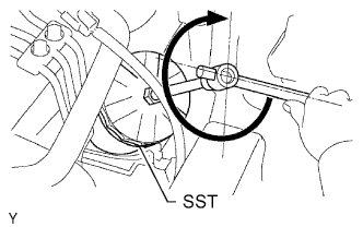
Using SST, hold the crankshaft pulley and install the set nut.
- SST
- 09213-58013
09330-00021
- Torque:
- 64 N*m{653 kgf*cm, 47 ft.*lbf}
 |
Move the pump drive shaft pulley back and forth to check the thrust clearance of the injection pump drive shaft.
- Standard thrust clearance:
- 0.15 to 0.55 mm (0.0059 to 0.0217 in.)
 |
Connect the 2 connectors.
 |
Connect the 2 fuel hoses.
 |
Temporarily install the fuel inlet pipe with the union nuts.
- NOTICE:
- If the supply pump is replaced, the fuel inlet pipe must be replaced.
- Keep the fuel inlet pipe free of foreign matter.
 |
Using union nut wrench, tighten the injection pipe union nut on the common rail side.
- Torque:
- 32 N*m{326 kgf*cm, 24 ft.*lbf} for use with union nut wrench
- 35 N*m{357 kgf*cm, 26 ft.*lbf} for use without union nut wrench
- HINT:
- Use a torque wrench with a fulcrum length of 30 cm (11.81 in.).
Using union nut wrench, tighten the injection pipe union nut on the supply pump side.
- Torque:
- 32 N*m{326 kgf*cm, 24 ft.*lbf} for use with union nut wrench
- 35 N*m{357 kgf*cm, 26 ft.*lbf} for use without union nut wrench
Install the oil dipstick guide with the bolt.
- Torque:
- 8.0 N*m{82 kgf*cm, 71 in.*lbf}
Install the clamp with the bolt.
- Torque:
- 5.0 N*m{51 kgf*cm, 44 in.*lbf}
 |
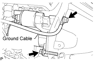
| 5. INSTALL STARTER ASSEMBLY |
Connect the ground cable and install the starter with the 2 bolts.
- HINT:
- Make sure to connect the ground cable with the bolt as shown in the illustration.
- Torque:
- 68 N*m{693 kgf*cm, 50 ft.*lbf}
 |
Install the starter wire to terminal 30 with the nut.
- Torque:
- 9.8 N*m{100 kgf*cm, 87 in.*lbf}
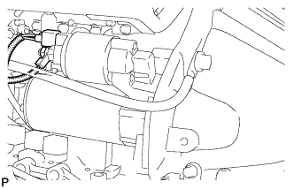 |
Connect the starter connector.
| 6. INSTALL OIL FILTER SUB-ASSEMBLY |
Check and clean the oil filter installation surface.
Apply clean engine oil to the gasket of a new oil filter.
Lightly screw the oil filter into place by hand. Tighten it until the gasket contacts the seat.
Using SST, tighten the oil filter. Depending on the work space available, choose from the following.
- SST
- 09228-07501
If enough space is available, use a torque wrench to tighten the oil filter.
- Torque:
- 12 N*m{122 kgf*cm, 9 ft.*lbf}
If enough space is not available to use a torque wrench, tighten the oil filter 3/4 turn by hand or with a common wrench.
 |
| 7. INSTALL INJECTION PIPE |
 |
- NOTICE:
- When replacing the injector, also replace the injection pipe.
- Keep the joints of the injection pipe clean.
Temporarily install the No. 1, No. 2 and No. 3 injection pipes with the union nuts.
Install the No. 2 and No. 3 injection pipe clamps with the bolt and 2 nuts, as shown in the illustration.
- Torque:
- 5.0 N*m{51 kgf*cm, 44 in.*lbf}
- HINT:
- If the painted mark on the No. 1 injection pipe has disappeared, use the illustration as a reference to install the clamps.
Using union nut wrench, tighten the injection pipe union nuts on the common rail side.
- Torque:
- 32 N*m{326 kgf*cm, 24 ft.*lbf} for use with union nut wrench
- 35 N*m{357 kgf*cm, 26 ft.*lbf} for use without union nut wrench
- HINT:
- Use a torque wrench with a fulcrum length of 30 cm (11.81 in.).
 |
Using union nut wrench, tighten the injection pipe union nuts on the injector side.
- Torque:
- 32 N*m{326 kgf*cm, 24 ft.*lbf} for use with union nut wrench
- 35 N*m{357 kgf*cm, 26 ft.*lbf} for use without union nut wrench
- HINT:
- Use a torque wrench with a fulcrum length of 30 cm (11.81 in.).
Temporarily install the No. 4 injection pipe with the union nuts.
 |
Install 2 new injection pipe clamps with the 2 bolts.
- Torque:
- 13 N*m{133 kgf*cm, 10 ft.*lbf}
- NOTICE:
- Make sure that the inner-rubbers of the injection pipe fit inside the clamps.
- When installing the pipe, check that the inner-rubbers and the clamps are in their proper positions.
Using union nut wrench, tighten the injection pipe union nut on the common rail side.
- Torque:
- 32 N*m{326 kgf*cm, 24 ft.*lbf} for use with union nut wrench
- 35 N*m{357 kgf*cm, 26 ft.*lbf} for use without union nut wrench
- HINT:
- Use a torque wrench with a fulcrum length of 30 cm (11.81 in.).
 |
Using union nut wrench, tighten the injection pipe union nut on the injector side.
- Torque:
- 32 N*m{326 kgf*cm, 24 ft.*lbf} for use with union nut wrench
- 35 N*m{357 kgf*cm, 26 ft.*lbf} for use without union nut wrench
- HINT:
- Use a torque wrench with a fulcrum length of 30 cm (11.81 in.).
| 8. INSTALL FUEL INLET PIPE SUB-ASSEMBLY |
|
Temporarily install the fuel inlet pipe with the union nuts.
- NOTICE:
- If the common rail is replaced, the fuel inlet pipe must be replaced.
- Be careful that dust, dirt or any other foreign matter does not contact the joint area of the fuel inlet pipe.
Using union nut wrench, tighten the inlet pipe union nut on the common rail side.
- Torque:
- 32 N*m{326 kgf*cm, 24 ft.*lbf} for use with union nut wrench
- 35 N*m{357 kgf*cm, 26 ft.*lbf} for use without union nut wrench
Using union nut wrench, tighten the inlet pipe union nut on the supply pump side.
- Torque:
- 32 N*m{326 kgf*cm, 24 ft.*lbf} for use with union nut wrench
- 35 N*m{357 kgf*cm, 26 ft.*lbf} for use without union nut wrench
Install the oil dipstick guide with the bolt.
- Torque:
- 8.0 N*m{82 kgf*cm, 71 in.*lbf}
Install the clamp with the bolt.
- Torque:
- 5.0 N*m{51 kgf*cm, 44 in.*lbf}
|
| 9. INSTALL OIL DIPSTICK GUIDE |
Apply clean engine oil to a new O-ring.
Install the O-ring to the guide.
Install the guide with the bolt.
- Torque:
- 8.0 N*m{82 kgf*cm, 71 in.*lbf}
| 10. INSTALL MANIFOLD STAY |
 |
Install the stay with the 2 bolts.
- Torque:
- 19 N*m{194 kgf*cm, 14 ft.*lbf}
| 11. ADD FUEL |
| 12. TIGHTEN FUEL TANK CAP ASSEMBLY |
| 13. BLEED AIR FROM FUEL SYSTEM |
 |
Using the hand pump, bleed air from the fuel system until pumping becomes difficult.
| 14. ADD ENGINE OIL |
Wipe the oil pan and drain plug.
Install a new gasket and the drain plug.
- Torque:
- 34 N*m{347 kgf*cm, 25 ft.*lbf}
Add new oil.
- Standard oil capacity:
Item Specified Condition Drain and refill with oil filter change 6.9 liters (7.3 US qts, 6.1 Imp. qts) Drain and refill without oil filter change 6.6 liters (7.0 US qts, 5.8 Imp. qts) Dry fill 7.4 liters (7.8 US qts, 6.5 Imp. qts)
Install the oil filler cap.
| 15. CONNECT CABLE TO NEGATIVE BATTERY TERMINAL |
| 16. CHECK FOR FUEL LEAKS |
- CAUTION:
- During Active Test mode, engine speed becomes high and combustion noise becomes loud, so pay attention.
- During Active Test mode, fuel becomes high-pressured. Be extremely careful not to expose your eyes, hands, or body to escaped fuel.
Check that there are no leaks from any part of the fuel system when the engine is stopped. If there is fuel leakage, repair or replace parts as necessary.
Start the engine and check that there are no leaks from any part of the fuel system. If there is fuel leakage, repair or replace parts as necessary.
Disconnect the return hose from the common rail.
Start the engine and check for fuel leaks from the return pipe.
If there is fuel leakage, replace the common rail.
Connect the intelligent tester to the DLC3.
Start the engine and push the intelligent tester main switch on.
Select the Fuel Leak test from the Active Test mode on the intelligent tester.
If the intelligent tester is not available, fully depress the accelerator pedal quickly. Increase the engine speed to the maximum and maintain that speed for 2 seconds. Repeat this operation several times.
Check that there are no leaks from any part of the fuel system.
- NOTICE:
- A return pipe leakage of less than 10 cc (0.6 cu in.) per minute is acceptable.
Reconnect the return hose to the common rail.
| 17. CHECK FOR ENGINE OIL LEAKS |
| 18. CHECK ENGINE OIL LEVEL |
| 19. INSTALL NO. 2 ENGINE UNDER COVER (for 4WD) |
Install the under cover with the 2 bolts.
- Torque:
- 28 N*m{286 kgf*cm, 21 ft.*lbf}
| 20. INSTALL NO. 1 ENGINE UNDER COVER (for 4WD) |
Install the under cover with the 4 bolts.
- Torque:
- 28 N*m{286 kgf*cm, 21 ft.*lbf}