Oil Pump -- Removal |
- NOTICE:
- When replacing the injectors (including shuffling the injectors between the cylinders), common rail or cylinder head, it is necessary to replace the injection pipes with new ones.
- When replacing the fuel supply pump, common rail, cylinder block, cylinder head, cylinder head gasket or timing gear case, it is necessary to replace the fuel inlet pipe with a new one.
- After removing the injection pipes, clean them with a brush and compressed air.
| 1. DISCONNECT CABLE FROM NEGATIVE BATTERY TERMINAL |
- NOTICE:
- When disconnecting the cable, some systems need to be initialized after the cable is reconnected (Toyota Fortuner RM000004W63000X.html).
| 2. DRAIN ENGINE OIL |
Remove the oil filler cap.
Remove the oil pan drain plug and gasket, and then drain the engine oil into a container.
Wipe the oil pan and drain plug.
Install a new gasket and the oil pan drain plug.
- Torque:
- 34 N*m{347 kgf*cm, 25 ft.*lbf}
| 3. DRAIN ENGINE COOLANT |
- CAUTION:
- Do not remove the radiator reservoir cap while the engine and radiator are still hot. Pressurized, hot engine coolant and steam may be released and cause serious burns.
Loosen the radiator drain cock plug.
- HINT:
- Collect the coolant in a container and dispose of it according to the regulations in your area.
Drain the coolant by removing the radiator reservoir cap and, using a wrench, remove the vent plug.
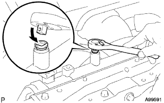 |
Loosen the cylinder block drain cock plug.
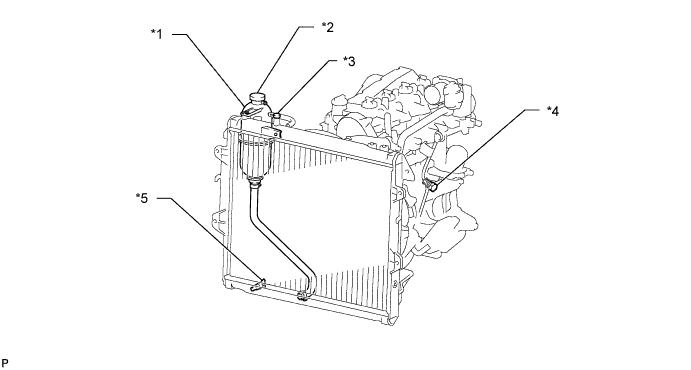
Text in Illustration *1 Radiator Reservoir *2 Radiator Reservoir Cap *3 Vent Plug *4 Cylinder Block Drain Cock Plug *5 Radiator Drain Cock Plug - -
| 4. REMOVE ENGINE ASSEMBLY |
| 5. REMOVE NO. 1 TIMING BELT COVER |
Remove the 6 bolts, 6 washers and timing belt cover.
 |
| 6. REMOVE TIMING BELT |
Turn the crankshaft clockwise and align the timing marks as shown in the illustration.
Text in Illustration *1 Timing Mark - HINT:
- If reusing the timing belt, place matchmarks on the timing belt so that it can be installed exactly as before.
 |
Uniformly loosen and remove the 2 bolts and No. 1 timing belt tensioner.
 |
Remove the timing belt.
- HINT:
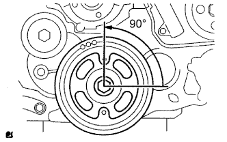
- If turning the camshaft while the timing belt is removed, turn the crankshaft 90° counterclockwise as shown in the illustration.
- When installing the timing belt, turn the camshaft to align the timing marks, and then turn the crankshaft clockwise to align the timing marks.
| 7. REMOVE NO. 1 TIMING BELT IDLER SUB-ASSEMBLY |
- NOTICE:
- When inspecting the No. 1 timing belt idler, do not remove it unless absolutely necessary.
Using a 10 mm hexagon wrench, remove the bolt, No. 1 timing belt idler and washer.
| 8. REMOVE NO. 2 IDLE PULLEY ASSEMBLY |
Remove the bolt, pulley plate, No. 2 idle pulley and spacer.
| 9. REMOVE GENERATOR ASSEMBLY |
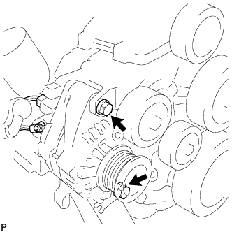 |
Remove the nut and generator wire.
Disconnect the generator connector.
Remove the 2 bolts and generator.
| 10. REMOVE GENERATOR BRACKET |
Remove the bolt and generator bracket.
| 11. REMOVE V-RIBBED BELT TENSIONER ASSEMBLY |
Remove the 4 bolts and V-ribbed belt tensioner.
 |
| 12. REMOVE NO. 1 COMPRESSOR MOUNTING BRACKET |
Remove the 4 bolts and No. 1 compressor mounting bracket.
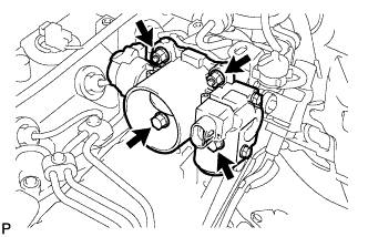
| 13. REMOVE DIESEL THROTTLE BODY ASSEMBLY |
Disconnect the 2 connectors.
 |
Remove the 2 bolts, 2 nuts, diesel throttle body and gasket.
 |
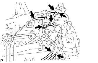
| 14. REMOVE MANIFOLD STAY |
Disconnect the vacuum switching valve connector.
 |
Disconnect the 3 vacuum transmitting hoses.
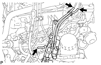 |
Remove the 2 bolts and manifold stay with vacuum switching valve.
 |
| 15. REMOVE NO. 1, NO. 2 AND NO. 3 INJECTION PIPE SUB-ASSEMBLY |
- NOTICE:
- After removing the fuel pipe, cover the outlets on the common rail with tape to keep out foreign matter.
- After removing the fuel pipe, put it in a plastic bag to prevent foreign matter from contaminating its injector inlet.
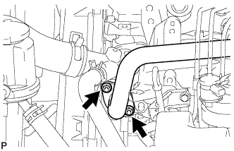
Remove the 2 nuts and No. 3 injection pipe clamp.
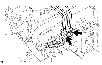 |
Remove the 2 bolts and 2 No. 2 injection pipe clamps.
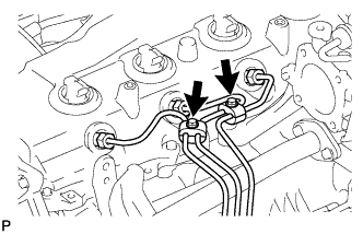 |
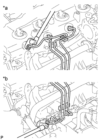
Using a 17 mm union nut wrench, loosen the union nuts and remove the No. 1, No. 2 and No. 3 injection pipes.
Text in Illustration *a Injector Side *b Common Rail Side
 |
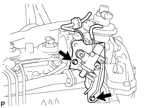
| 16. REMOVE NO. 2 INTAKE AIR CONNECTOR BRACKET |
Remove the 3 bolts and No. 2 intake air connector bracket.
 |
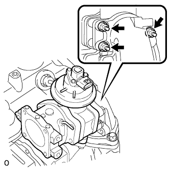
| 17. REMOVE ELECTRIC VACUUM REGULATING VALVE ASSEMBLY |
Disconnect the 2 connectors.
 |
Disconnect the 6 vacuum hoses.
 |
Remove the bolt and No. 1 gas filter with gas filter bracket.
Remove the 2 bolts and electric vacuum regulating valve.
 |
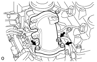
| 18. REMOVE NO. 2 INTAKE AIR CONNECTOR |
Remove the 3 nuts, No. 2 intake air connector and gasket.
 |
| 19. REMOVE INTAKE AIR CONNECTOR |
Remove the 3 bolts, intake air connector and 2 gaskets.
 |
| 20. REMOVE ELECTRIC EGR CONTROL VALVE WITH NO. 1 EGR PIPE SUB-ASSEMBLY |
Remove the 2 nuts, electric EGR control valve with No. 1 EGR pipe and gasket.
 |
| 21. REMOVE NO. 4 INJECTION PIPE SUB-ASSEMBLY |
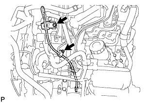
Remove the bolt and disconnect the injection pipe clamp.
- NOTICE:
- If an injection pipe clamp is removed from the No. 4 injection pipe, replace the injection clamp with a new one.
 |
Using a 17 mm union nut wrench, loosen the union nuts and remove the No. 4 injection pipe.
Text in Illustration *a Injector Side *b Common Rail Side
 |
| 22. REMOVE ENGINE OIL LEVEL DIPSTICK GUIDE |
Remove the engine oil level dipstick.
Remove the bolt and injection pipe clamp.
 |
Remove the bolt and engine oil level dipstick guide.
Remove the O-ring from the engine oil level dipstick guide.
| 23. REMOVE FUEL INLET PIPE SUB-ASSEMBLY |
Using a 17 mm union nut wrench, loosen the union nuts and remove the fuel inlet pipe.
Text in Illustration *a Common Rail Side *b Fuel Supply Pump Side
 |
| 24. REMOVE NO. 2 NOZZLE LEAKAGE PIPE ASSEMBLY |
Disconnect the 3 fuel hoses.
Remove the union bolt, 3 bolts, No. 2 nozzle leakage pipe and gasket.
Text in Illustration *1 Union Bolt
 |
| 25. REMOVE CYLINDER HEAD COVER SUB-ASSEMBLY |
Remove the 3 bolts and disconnect the 4 connectors.
 |
Disconnect the ventilation hose.
Using a small screwdriver, remove the nozzle holder seal by prying between the nozzle holder seal and the cutout part of the cylinder head cover.
 |
Remove the 10 bolts, 2 nuts, cylinder head cover and cylinder head cover gasket.
 |
| 26. REMOVE CAMSHAFT TIMING PULLEY |
Remove the bolt of the camshaft timing pulley while holding the camshaft with a wrench.
- NOTICE:
- Make sure to remove the bolt of the camshaft timing pulley with the timing belt not installed.
 |
Remove the camshaft timing pulley.
| 27. REMOVE NO. 2 TIMING BELT COVER |
Remove the 4 bolts, nut and timing belt cover.
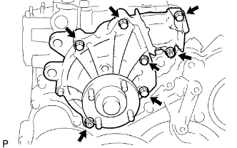
| 28. REMOVE WATER PUMP ASSEMBLY |
Remove the 5 bolts, 2 nuts, water pump and gasket.
 |
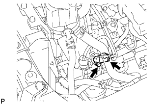
| 29. REMOVE VACUUM PUMP ASSEMBLY |
Remove the 2 nuts, vacuum pump and 2 O-rings.
 |
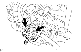
| 30. REMOVE VANE PUMP ASSEMBLY |
Remove the 2 nuts, vane pump and O-ring.
 |
| 31. REMOVE CAMSHAFT POSITION SENSOR |
Disconnect the camshaft position sensor connector.
 |
Remove the bolt and camshaft position sensor.
| 32. REMOVE CRANKSHAFT POSITION SENSOR |
Disconnect the crankshaft position sensor connector.
Detach the 4 clips and remove the bolt and crankshaft position sensor.

| 33. REMOVE PUMP DRIVE SHAFT PULLEY |
Remove the 4 bolts, No. 2 camshaft timing pulley flange and pump drive shaft pulley.
 |
Using SST, hold the crankshaft pulley and remove the nut and O-ring.
- SST
- 09213-58014
09330-00021
 |
| 34. REMOVE CRANKSHAFT PULLEY |
Using SST, hold the crankshaft pulley and loosen the pulley bolt.
- SST
- 09213-58014
09330-00021
 |
Using SST, remove the pulley bolt and crankshaft pulley.
- SST
- 09950-50013(09951-05010,09952-05010,09953-05020,09954-05021)
 |
| 35. REMOVE TIMING GEAR COVER |
- NOTICE:
- As the fuel supply pump is not installed, the injection gear is loose inside the timing gear case. Do not allow the injection gear to fall.
- HINT:
- To prevent the injection gear from falling, temporarily install the fuel supply pump.
Remove the 14 bolts and 2 nuts.
 |
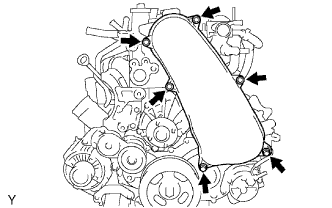
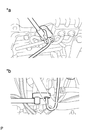
Pry the timing gear cover at the locations shown in the illustration and remove the timing gear cover.
- NOTICE:
- Be careful not to drop the injection gear.
 |
Remove the O-ring from the timing gear case.
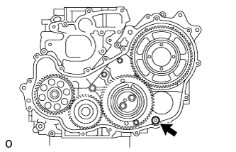 |
| 36. REMOVE INJECTION GEAR |
Secure the No. 2 idle sub gear to the No. 1 idle gear with a service bolt.
- Torque:
- 8.0 N*m{82 kgf*cm, 71 in.*lbf}
- NOTICE:
- If the bolt hole of the No. 2 idle sub gear is not aligned with the bolt hole of the No. 1 idle gear, rotate the crankshaft counterclockwise to align the bolt holes. Then install the service bolt.
 |
Remove the injection gear.
 |
| 37. REMOVE NO. 1 CRANKSHAFT POSITION SENSOR PLATE |
Remove the No. 1 crankshaft position sensor plate.
 |
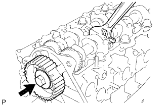
| 38. REMOVE CRANKSHAFT TIMING GEAR |
Using SST, remove the crankshaft timing gear.
- SST
- 09950-50013(09951-05010,09952-05010,09953-05010,09954-05021)
 |
| 39. REMOVE IDLE GEAR THRUST PLATE |
Remove the 2 bolts and idle gear thrust plate.
 |
| 40. REMOVE NO. 1 IDLE GEAR |
Remove the No. 1 idle gear together with the No. 2 idle sub gear.
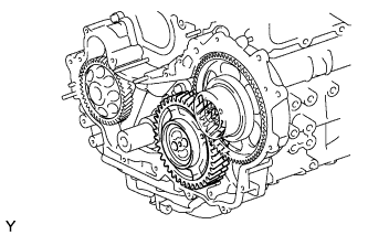 |
| 41. REMOVE NO. 1 IDLE GEAR SHAFT |
Remove the No. 1 idle gear shaft.
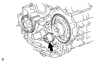 |
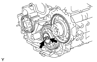
| 42. REMOVE FUEL SUPPLY PUMP ASSEMBLY |
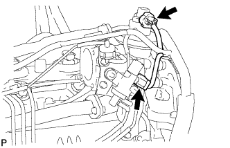
Disconnect the 2 fuel hoses.
 |
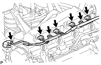
Disconnect the fuel temperature sensor connector and suction control valve connector.
 |
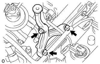
Remove the 4 bolts indicated by the arrows in the illustration.
 |
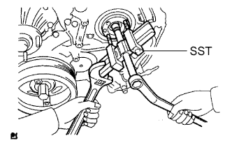
Remove the No. 2 camshaft timing pulley flange and pump drive shaft pulley.
Remove the set nut and O-ring while holding the crankshaft pulley using SST.
- SST
- 09213-58014
09330-00021
 |
Loosen the 2 nuts.
 |
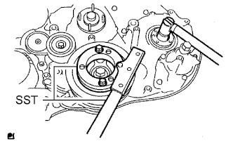
Using SST, disconnect the fuel supply pump from the injection gear.
- SST
- 09950-50013(09951-05010,09952-05010,09953-05020,09954-05021)
- NOTICE:
- Apply lubricant to the threads and tip of SST (center bolt) before using it.
 |
Remove the 2 nuts and fuel supply pump.
- NOTICE:
- Do not hold or carry the fuel supply pump by the pipe.
- The fuel supply pump must be kept horizontal.
Remove the O-ring.
| 43. REMOVE OIL PAN SUB-ASSEMBLY |
Remove the 22 bolts and 2 nuts.
Insert the blade of an oil pan seal cutter between the oil pan and cylinder block, cut through the applied sealer and remove the oil pan.
- NOTICE:
- Do not use the oil pan seal cutter for the area between the oil pan and timing belt case, or for the area between the oil pan and rear oil seal retainer.
- Be careful not to damage the oil pan flange.
 |
| 44. REMOVE OIL STRAINER SUB-ASSEMBLY |
Remove the 2 bolts, 2 nuts, oil strainer and gasket.
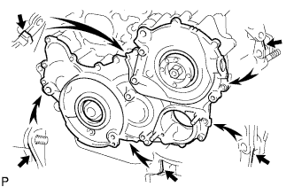
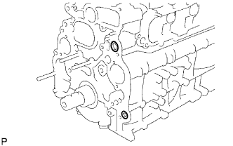
| 45. REMOVE TIMING GEAR CASE ASSEMBLY |
Remove the bolt and No. 1 vacuum transmitting pipe.
Remove the union bolt and 8 bolts.
 |
Pry the timing gear case at the location shown in the illustration and remove the gear case and gasket.
Remove the 2 O-rings.
 |