Air Fuel Ratio Sensor -- On-Vehicle Inspection |
| 1. CHECK AIR FUEL RATIO SENSOR (for Sensor 1) |
 |
Disconnect the sensor connector.
Measure the resistance of the sensor.
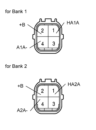
- Bank 1 standard resistance:
Tester Connection Specified Condition 1 (HA1A) - 2 (+B) 1.8 to 3.4 Ω at 20°C (68°F) 1 (HA1A) - 4 (A1A-) 10 kΩ or higher
- Bank 2 standard resistance:
Tester Connection Specified Condition 1 (HA2A) - 2 (+B) 1.8 to 3.4 Ω at 20°C (68°F) 1 (HA2A) - 4 (A2A-) 10 kΩ or higher
Connect the sensor connector.
| 2. CHECK AIR FUEL RATIO COMPENSATION SYSTEM |
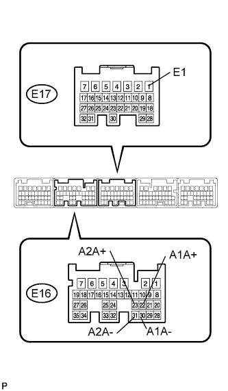 |
Measure the voltage between the terminals of the ECM.
- Standard voltage:
Tester Connection Condition Specified Condition E16-22 (A1A+) - E17-1 (E1) Ignition switch ON 3.3 V E16-30 (A1A-) - E17-1 (E1) Ignition switch ON 3.3 V E16-23 (A2A+) - E17-1 (E1) Ignition switch ON 3.0 V E16-31 (A2A-) - E17-1 (E1) Ignition switch ON 3.0 V
- NOTICE:
- Connect test leads from the backside of the ECM connector with the ECM connected.
- HINT:
- Voltage between the terminals of the ECM is kept constant regardless of the voltage of the A/F sensor.
Connect the intelligent tester to the DLC3.
Select "DATA MONITOR" - "A/FS B1 S1", "A/FS B2 S1" and "O2S B1 S2" to display the monitor.
Warm up the A/F sensor with the engine speed at 2,500 rpm for approximately 2 minutes.
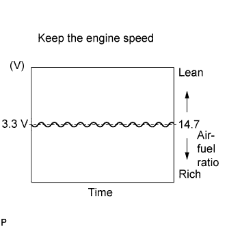
Keep the engine speed at 2,500 rpm and confirm that the displays of "A/FS B1S1" and "A/FS B2 S1" are similar to the illustration.
- HINT:
- The illustration differs from the real display.
- Only the intelligent tester displays the waveform of the A/F sensor.
 |
Confirm that the display of "O2S B1 S2" changes between 0 to 1 V with the engine speed at 2,500 rpm.