Cylinder Head -- Removal |
- NOTICE:
- When replacing the injectors (including shuffling the injectors between the cylinders), common rail or cylinder head, it is necessary to replace the injection pipes with new ones.
- When replacing the fuel supply pump, common rail, cylinder block, cylinder head, cylinder head gasket or timing gear case, it is necessary to replace the fuel inlet pipe with a new one.
| 1. DISCONNECT CABLE FROM NEGATIVE BATTERY TERMINAL |
- CAUTION:
- Wait at least 90 seconds after disconnecting the cable from the negative (-) battery terminal to prevent airbag and seat belt pretensioner activation.
| 2. DRAIN ENGINE OIL |
Remove the oil filler cap.
Remove the oil drain plug, and drain the engine oil from the oil pan.
- NOTICE:
- Collect the oil in an oil disposal container.
| 3. LOOSEN FUEL TANK CAP ASSEMBLY |
| 4. DRAIN FUEL |
| 5. REMOVE FRONT EXHAUST PIPE ASSEMBLY |
Remove the 2 bolts and 2 compression springs.
Disconnect the front pipe from the outlet pipe and remove the gasket.
Remove the front pipe from the pipe support.
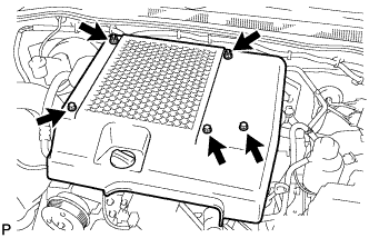
| 6. REMOVE NO. 1 ENGINE COVER SUB-ASSEMBLY |
Remove the 3 bolts, 2 nuts and engine cover.
 |
| 7. REMOVE CHARGE AIR COOLER ASSEMBLY WITH INTAKE AIR CONNECTOR |
Disconnect the IAT sensor connector.
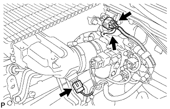 |
Disconnect the manifold absolute diesel pressure sensor connector.
Disconnect the vacuum hose from the manifold absolute pressure sensor.
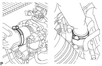
Loosen the 2 clamps.
 |
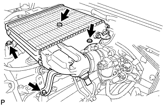
Remove the 4 bolts and CAC.
 |
| 8. REMOVE AIR CLEANER ASSEMBLY |
Disconnect the MAF meter connector.
Loosen the hose clamp.
Remove the 2 bolts and air cleaner.
| 9. REMOVE VENTILATION PIPE |
| 10. REMOVE FAN SHROUD |
Remove the fan shroud (Toyota Fortuner RM0000014Y2007X_01_0005.html).
| 11. REMOVE FAN PULLEY |
| 12. DISCONNECT COOLER COMPRESSOR ASSEMBLY |
Remove the 4 bolts and disconnect the cooler compressor.
- HINT:
- It is not necessary to completely remove the compressor. With the hoses connected to the compressor, hang the compressor on the vehicle body with a rope.
| 13. REMOVE NO. 1 COMPRESSOR MOUNTING BRACKET |
Remove the 4 bolts and mounting bracket.
| 14. REMOVE EXHAUST MANIFOLD |
 |
Remove the 8 nuts and exhaust manifold w/turbocharger.
| 15. REMOVE MANIFOLD STAY |
 |
Remove the 2 bolts and stay.
| 16. DISCONNECT WIRE HARNESS |
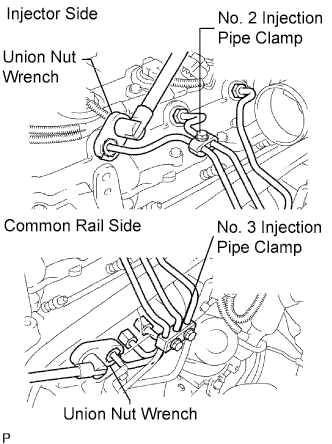
| 17. REMOVE INJECTION PIPE |
 |
- NOTICE:
- After removing the fuel pipe, cover the outlets on the common rail with tape to keep out foreign matter.
- After removing the fuel pipe, put it in a plastic bag to prevent foreign matter from contaminating its injector inlet.
Remove the 2 nuts and No. 3 injection pipe clamp.
Remove the bolt and No. 2 injection pipe clamp.
Using union nut wrench, loosen the union nuts and remove the No. 1, No. 2 and No. 3 injection pipes.
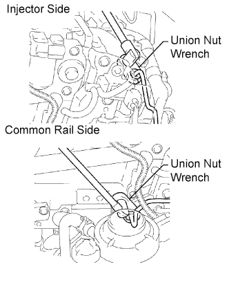
Remove the 2 bolts and disconnect the 2 injection pipe clamps.
Using union nut wrench, loosen the union nuts and remove the No. 4 injection pipe.

| 18. REMOVE NO. 2 NOZZLE LEAKAGE PIPE ASSEMBLY |
Disconnect the 2 fuel hoses.
 |
Remove the check valve, 3 bolts, leakage pipe and gasket.
| 19. REMOVE EGR VALVE ASSEMBLY |
Remove the EGR valve and gasket.
| 20. REMOVE INTAKE MANIFOLD |
 |
Remove the 4 bolts, 2 nuts, manifold and gasket.
| 21. REMOVE NO. 1 TIMING BELT COVER |
 |
Remove the bolt and water hose clamp.
Remove the wire harness clamp.
Remove the 6 bolts and timing belt cover.
| 22. REMOVE TIMING BELT |
 |
Turn the crankshaft clockwise and align the timing marks as shown in the illustration.
Uniformly loosen the 2 bolts and remove the timing belt tensioner.
 |
Remove the timing belt.
Using a 10 mm hexagon wrench, remove the bolt, timing belt idler and washer.
- HINT:
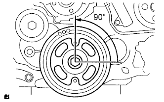
- When turning the camshaft while the timing belt is removed, turn the crankshaft 90° counterclockwise as shown in the illustration.
- When installing the timing belt, return the camshaft to the timing marks and then turn the crankshaft clockwise until it aligns with the timing marks.
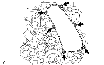
| 23. REMOVE CYLINDER HEAD COVER SUB-ASSEMBLY |
 |
Using a small screwdriver, remove the 4 holder seals by prying the portion between each holder seal and the cutout part of the cylinder head.
Remove the 10 bolts, 2 nuts, cylinder head cover and gasket.
 |
| 24. REMOVE CAMSHAFT TIMING PULLEY |
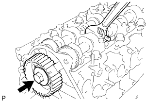 |
Remove the bolt of the camshaft timing pulley by holding the camshaft with a wrench.
- NOTICE:
- Make sure to remove the bolt of the camshaft timing pulley with the timing belt not installed.
Remove the camshaft timing pulley.
| 25. REMOVE NO. 1 TIMING BELT IDLER SUB-ASSEMBLY |
| 26. REMOVE NO. 2 TIMING BELT COVER |
Remove the 4 bolts, nut and timing belt cover.
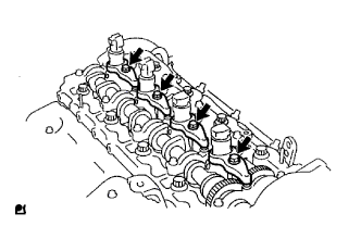
| 27. REMOVE INJECTOR ASSEMBLY |
 |
Remove the union bolt, 4 hollow screws, 5 gaskets and nozzle leakage pipe.
- NOTICE:
- When removing the nozzle leakage pipe, place a cushion under the pipe.
- Be careful not to deform or scratch the union seal surface.
- After removing the fuel pipe, put it in a plastic bag to prevent foreign matter from contaminating its injector inlet.
Remove the 4 bolts, 4 washers, 4 nozzle holder clamps and 4 injectors.
- HINT:
- Arrange the injectors, holder clamps, washers and bolts in the correct order.
 |
Remove the O-ring and back-up ring from each injector.
Remove the 4 injection nozzle sheets from the cylinder head.
| 28. REMOVE CAMSHAFT |
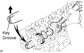 |
Face the key groove of the camshaft upward by turning the camshaft with a wrench.
Uniformly loosen the 15 bearing cap bolts in several passes in the sequence shown in the illustration.
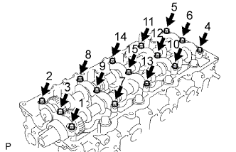 |
Remove the 5 bearing caps, oil seal and 2 camshafts.
| 29. REMOVE CYLINDER HEAD SUB-ASSEMBLY |
 |
Uniformly loosen the 18 cylinder head bolts in several passes in the sequence shown in the illustration. Then remove the 18 cylinder head bolts and 18 washers.
- NOTICE:
- Head warpage or cracking could result from removing bolts in the incorrect order.
Lift the cylinder head from the dowels on the cylinder block, and place the cylinder head on wooden blocks on a bench.
- HINT:
- If the cylinder head is difficult to lift, use a screwdriver to pry between the cylinder head and block.
- NOTICE:
- Be careful not to damage the contact surfaces of the cylinder head and cylinder block.
| 30. REMOVE CYLINDER HEAD GASKET |