Cylinder Head -- Installation |
- NOTICE:
- When replacing the injectors (including shuffling the injectors between the cylinders), common rail or cylinder head, it is necessary to replace the injection pipes with new ones.
- When replacing the fuel supply pump, common rail, cylinder block, cylinder head, cylinder head gasket or timing gear case, it is necessary to replace the fuel inlet pipe with a new one.
| 1. INSTALL CYLINDER HEAD GASKET |
Check the piston protrusions for each cylinder.
Clean the cylinder block with solvent.
Set the piston of the cylinder to be measured to slightly before TDC.
Place a dial indicator on the cylinder block, and set the measuring tip as shown in the illustration.
Set the dial indicator at 0 mm (0 in.)
- HINT:
- Make sure that the measuring tip is square to the cylinder block gasket surface and piston head when taking the measurements.
 |
Find where the piston head protrudes most by slowly turning the crankshaft clockwise and counterclockwise.
Measure the piston protrusion of each cylinder at the 2 points shown in the illustration.
 |
For the piston protrusion value of each cylinder, use the average of the 2 measurements of each cylinder.
- Standard piston protrusion:
- 0.005 to 0.254 mm (0.0002 to 0.0100 in.)
- HINT:
- When installing the piston and connecting rod assembly, if the protrusion is not as specified, remove the piston and connecting rod assembly and reinstall them.
Select a new cylinder head gasket.
- HINT:
- New cylinder head gaskets are available in 5 sizes, and are marked A, B, C, D or E.
- New installed cylinder head gasket thickness:
Mark Thickness A 0.80 to 0.90 mm (0.0315 to 0.0354 in.) B 0.85 to 0.95 mm (0.0335 to 0.0374 in.) C 0.90 to 1.00 mm (0.0354 to 0.0394 in.) D 0.95 to 1.05 mm (0.0374 to 0.0413 in.) E 1.00 to 1.10 mm (0.0394 to 0.0433 in.)
Select the largest piston protrusion value from the measurements made. Then select a new appropriate gasket according to the table below.
- Use gasket size:
Gasket Size Piston Protrusion Use A 0.005 to 0.054 mm (0.0002 to 0.0021 in.) Use B 0.055 to 0.104 mm (0.0022 to 0.0041 in.) Use C 0.105 to 0.154 mm (0.0041 to 0.0061 in.) Use D 0.155 to 0.204 mm (0.0061 to 0.0080 in.) Use E 0.205 to 0.255 mm (0.0081 to 0.0100 in.)
 |
Place the cylinder head on the cylinder block.
Place the cylinder head gasket on the cylinder block.
- NOTICE:
- Be careful of the installation direction.
Place the cylinder head on the cylinder head gasket.
 |
| 2. INSTALL CYLINDER HEAD SUB-ASSEMBLY |
 |
- HINT:
- The cylinder head bolts are tightened in 3 progressive steps.
- If any bolt is broken or deformed, replace it.
Apply a light coat of engine oil on the threads and under the heads of the cylinder head bolts.
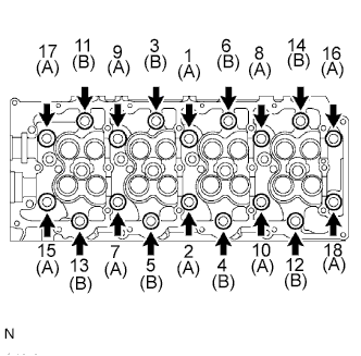
Install and uniformly tighten the 18 cylinder head bolts and 18 washers, in several passes in the sequence shown in the illustration.
- Torque:
- 85 N*m{867 kgf*cm, 63 ft.*lbf}
- HINT:
- Each bolt length is indicated below.
- Bolt length:
- 110 mm (4.33 in.) for bolt A
167 mm (6.57 in.) for bolt B
Mark the front of the cylinder head bolts with paint.
 |
Further tighten the cylinder head bolts by 90° in the sequence shown in the illustration above.
Finally, tighten the cylinder head bolts by an additional 90°.
Check that the painted mark is now facing rearward.
| 3. INSTALL CAMSHAFT |
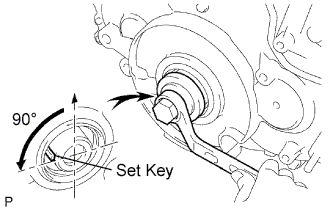 |
Using the crankshaft pulley bolt, set the No. 1 cylinder to 90° BTDC/compression.
- HINT:
- Set the No. 1 cylinder to 90° BTDC/compression to avoid interference with the piston top and valve head.
Install the camshaft.
Apply MP grease to the thrust portion of the camshaft.
Place the camshaft on the cylinder head, facing the key groove upward.
Align the timing marks (1 dot mark) of the camshaft drive and driven main gears, and set the No. 2 camshaft in place.

 |
Remove any old packing (FIPG) material from the camshaft bearing cap.
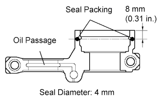 |
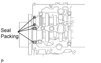
Apply seal packing to the specified areas shown in the illustration.
- Seal packing:
- Toyota Genuine Seal Packing Black, Three Bond 1207B or equivalent
- Standard seal diameter:
- 4 mm (0.16 in.)
- NOTICE:
- Do not allow FIPG to contact the oil passage of the bearing cap.
- After applying FIPG, install the camshaft bearing caps within 3 minutes and fasten the bolts within 15 minutes.
- Do not start the engine for at least 2 hours after the installation.
Install the 5 bearing caps in their proper locations.
Apply a light coat of engine oil on the threads and under the heads of the bearing cap bolts.
Install and uniformly tighten the 15 bearing cap bolts in several passes in the sequence shown in the illustration.
- Torque:
- 19 N*m{194 kgf*cm, 14 ft.*lbf}


Install the camshaft oil seal.
Apply MP grease to the lip of a new oil seal.
Using SST and a hammer, tap in the oil seal until its surface is flush with the oil seal retainer edge.
- SST
- 09608-06041

| 4. INSPECT VALVE CLEARANCE |
 |
Check only the valves indicated.
Using a feeler gauge, measure the clearance between the valve lifter and camshaft.
- Standard valve clearance (Cold):
Intake Exhaust 0.20 to 0.30 mm (0.008 to 0.012 in.) 0.35 to 0.45 mm (0.014 to 0.018 in.)
Turn the crankshaft 360° to set the No. 4 cylinder to TDC / compression.
Check only the valves indicated.
Using a feeler gauge, measure the clearance between the valve lifter and camshaft.
- Standard valve clearance:
Intake Exhaust 0.20 to 0.30 mm (0.008 to 0.012 in.) 0.35 to 0.45 mm (0.014 to 0.018 in.)
 |
| 5. ADJUST VALVE CLEARANCE |
Remove the injector.
Remove the timing belt.
Remove the camshaft timing pulley.
Remove the No. 2 timing belt cover.
Remove the camshafts.
Remove the valve lifters.
Determine the replacement valve lifter size by following the procedures below.
Using a micrometer, measure the thickness of the removed lifter.
Calculate the thickness of a new lifter so that the valve clearance comes within the specified value.
A B C New lifter thickness Used lifter thickness Measured valve clearance - New lifter thickness:
- Intake A = B + (C - 0.25 mm (0.0098 in.))
- Exhaust A = B + (C - 0.40 mm (0.00158 in.))
Select a new lifter with a thickness as close as possible to the calculated values.
- HINT:
- Valve lifters are available in 35 sizes in increments of 0.020 mm (0.0008 in.), from 5.060 mm (0.1992 in.) to 5.740 mm (0.2260 in.).

Valve lifter selection chart (intake) (continued).
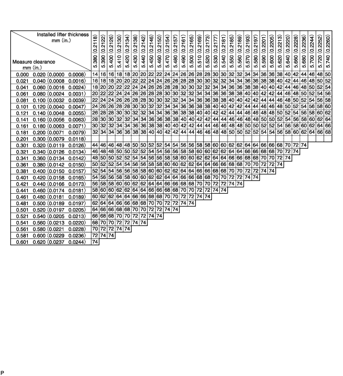
- Standard intake valve clearance (Cold):
- 0.20 to 0.30 mm (0.008 to 0.012 in.)
- EXAMPLE:
- The 5.250 mm (0.2067 in.) lifter is installed, and the measured clearance is 0.400 mm (0.0158 in.). Replace the 5.250 mm (0.2067 in.) shim with a No. 40 lifter.
- New lifter thickness (mm (in.)):
Shim No. Thickness Shim No. Thickness Shim No. Thickness 06 5.060 (0.1992) 30 5.300 (0.2087) 54 5.540 (0.2181) 08 5.080 (0.2000) 32 5.320 (0.2094) 56 5.560 (0.2189) 10 5.100 (0.2008) 34 5.340 (0.2102) 58 5.580 (0.2197) 12 5.120 (0.2016) 36 5.360 (0.2110) 60 5.600 (0.2205) 14 5.140 (0.2024) 38 5.380 (0.2118) 62 5.620 (0.2213) 16 5.160 (0.2031) 40 5.400 (0.2126) 64 5.640 (0.2220) 18 5.180 (0.2039) 42 5.420 (0.2134) 66 5.660 (0.2228) 20 5.200 (0.2047) 44 5.440 (0.2142) 68 5.680 (0.2236) 22 5.220 (0.2055) 46 5.460 (0.2150) 70 5.700 (0.2244) 24 5.240 (0.2063) 48 5.480 (0.2157) 72 5.720 (0.2252) 26 5.260 (0.2071) 50 5.500 (0.2165) 74 5.740 (0.2260) 28 5.280 (0.2079) 52 5.520 (0.2173) - -
Valve lifter selection chart (exhaust).

Valve lifter selection chart (exhaust) (continued).
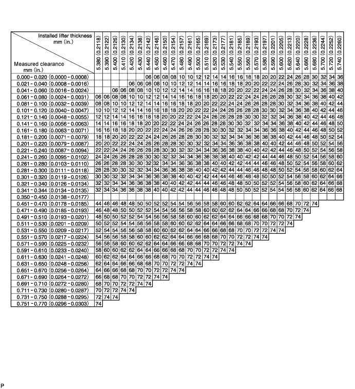
- Standard exhaust valve clearance (Cold):
- 0.35 to 0.45 mm (0.014 to 0.018 in.)
- EXAMPLE:
- The 5.340 mm (0.2102 in.) lifter is installed, and the measured clearance is 0.480 mm (0.0189 in.). Replace the 5.340 mm (0.2102 in.) shim with a No. 42 lifter.
- New lifter thickness (mm (in.)):
Shim No. Thickness Shim No. Thickness Shim No. Thickness 06 5.060 (0.1992) 30 5.300 (0.2087) 54 5.540 (0.2181) 08 5.080 (0.2000) 32 5.320 (0.2094) 56 5.560 (0.2189) 10 5.100 (0.2008) 34 5.340 (0.2102) 58 5.580 (0.2197) 12 5.120 (0.2016) 36 5.360 (0.2110) 60 5.600 (0.2205) 14 5.140 (0.2024) 38 5.380 (0.2118) 62 5.620 (0.2213) 16 5.160 (0.2031) 40 5.400 (0.2126) 64 5.640 (0.2220) 18 5.180 (0.2039) 42 5.420 (0.2134) 66 5.660 (0.2228) 20 5.200 (0.2047) 44 5.440 (0.2142) 68 5.680 (0.2236) 22 5.220 (0.2055) 46 5.460 (0.2150) 70 5.700 (0.2244) 24 5.240 (0.2063) 48 5.480 (0.2157) 72 5.720 (0.2252) 26 5.260 (0.2071) 50 5.500 (0.2165) 74 5.740 (0.2260) 28 5.280 (0.2079) 52 5.520 (0.2173) - -

Install the selected valve lifter.
Install the camshaft.
Install the No. 2 timing belt cover.
Install the camshaft timing pulley.
Install the timing belt.
Install the fuel injector.
| 6. INSTALL INJECTOR ASSEMBLY |
- NOTICE:
- Be sure to install the injector, holder clamp, washer and bolt in their original positions.
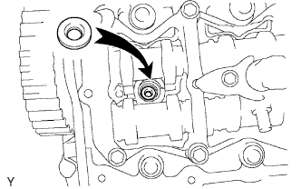
Install 4 new injection nozzle sheets to the cylinder head.
 |
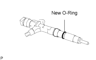
Apply a light amount of clean engine oil to 4 new O-rings.
Install an O-ring to each injector as shown in the illustration.
 |
Insert the 4 injectors into the cylinder head.
- NOTICE:
- Insert the injector until it touches the nozzle sheet surface.
- After installing the injector to the cylinder head, the O-ring may prevent the injector from fully seating. If so, pull out the injector and reinstall it.
- Always reinstall an injector to the same place it was removed from.
For an injector that has been replaced with a new injector, register the injector compensation code (Toyota Fortuner RM0000012XK005X.html).
Temporarily install 4 new washers and the 4 nozzle clamps with the 4 clamp bolts.
- HINT:
- Apply a light amount of engine oil to the threads and under the heads of the clamp bolts.
- NOTICE:
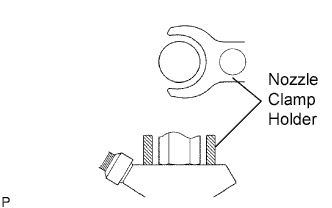
- The fork portion of the nozzle holder clamp must be set to the injector.
- Before tightening the bolts, check that the nozzle holder clamp is set properly.
- To fasten the clamp bolts, first tighten them by hand until they cannot be turned further. Then, tighten the bolts to the specified torque in the following step.
- When tightening the bolts, be careful not to tilt the bolt and clamp.
- Do not reuse the washer.
- If the nozzle leakage pipe is accidentally tightened beyond the torque specification, it must be replaced.
 |
Temporarily install the 4 injection pipes with the union nuts.
- HINT:
- To position the injectors, loosely tighten the union nut.
Check the nozzle leakage pipe. Check that there are no scratches or dents on the 5 union seal surfaces.
If scratches or dents are present, replace the nozzle leakage pipe.
 |
Set the leakage pipe and 5 new gaskets in place.
 |
Apply a light amount of oil to the 4 hollow screws and union bolt.
Temporarily install the leakage pipe with the 4 hollow screws and union bolt.
 |
Tighten the 4 holder clamp bolts.
- Torque:
- 22 N*m{224 kgf*cm, 16 ft.*lbf}
Tighten the 4 hollow screws in order from 1 to 4.
- Torque:
- 16 N*m{163 kgf*cm, 12 ft.*lbf}
- NOTICE:
- If a hollow screw is accidentally tightened beyond the torque specification, it must be replaced.
 |
Tighten the union bolt.
- Torque:
- 12.5 N*m{127 kgf*cm, 9 ft.*lbf}
- NOTICE:
- If the union bolt is accidentally tightened beyond the torque specification, it must be replaced.
Remove the 4 injection pipes.
| 7. CHECK FOR FUEL LEAKS |
 |
Check that there are no leaks from the nozzle leakage pipe connection.
Install the gasket and No. 2 nozzle leakage pipe to the cylinder head with SST (check valve).
- Part No.:
- 23762-27010 (No. 2 nozzle leakage pipe)
- SST
- 09280-00010
- Torque:
- 21 N*m{214 kgf*cm, 16 ft.*lbf}
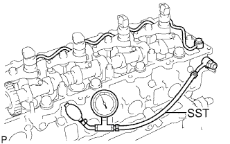
Apply a light amount of soapy water (or other fluid for detecting fuel leakage) on the nozzle leakage pipe connection.
Install SST (turbocharger pressure gauge) to the fuel return side of the leakage pipe, and maintain 100 kPa (1.0 kgf/cm2, 14.5 psi) of pressure for 60 seconds to check that no bubbles form.
- SST
- 09992-00242
- NOTICE:
- Before checking the leakage, be sure to remove the ball and spring in the check valve.
After checking for fuel leaks, wipe off the soapy water from the leakage pipe connection.
Remove SST, No. 2 nozzle leakage pipe and gasket.
- SST
- 09280-00010
09992-00242
- HINT:
- Never reinstall the disassembled check valve on the engine.
| 8. INSTALL NO. 2 TIMING BELT COVER |
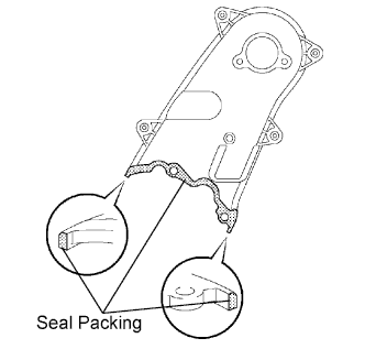 |
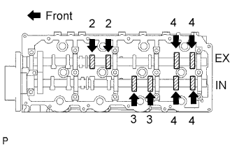
Apply seal packing (FIPG) to the specified areas shown in the illustration.
- Seal packing:
- Toyota Genuine Seal Packing Black, Three Bond 1207B or equivalent
- NOTICE:
- After applying FIPG, install the No. 2 timing belt cover within 3 minutes and tighten its bolts and nut within 15 minutes.
Install the No. 2 timing belt cover with the 4 bolts and nut.
- Torque:
- 10 N*m{102 kgf*cm, 7 ft.*lbf}
| 9. INSTALL CAMSHAFT TIMING PULLEY |
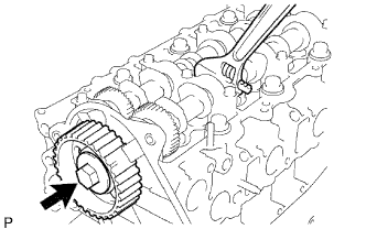 |
Install the camshaft timing pulley.
Fasten the bolt of the camshaft timing pulley by holding the camshaft with a wrench.
- Torque:
- 98 N*m{1,000 kgf*cm, 72 ft.*lbf}
| 10. INSTALL CYLINDER HEAD COVER SUB-ASSEMBLY |
 |
Remove any old seal packing (FIPG) material from the cylinder head.
Apply seal packing to the specific areas shown in the illustration.
- Seal packing:
- Toyota Genuine Seal Packing Black, Three Bond 1207B or equivalent
- NOTICE:
- Remove any oil from the contact surface.
- Install the belt cover within 3 minutes after applying seal packing.
- Do not start the engine for at least 2 hours after installing the seal packing.
Install the gasket and cylinder head cover with the 10 bolts and 2 nuts.
- Torque:
- 9.0 N*m{92 kgf*cm, 80 in.*lbf}
 |
Install 4 new nozzle holder seals.
| 11. INSTALL NO. 1 TIMING BELT IDLER SUB-ASSEMBLY |
| 12. INSTALL TIMING BELT |
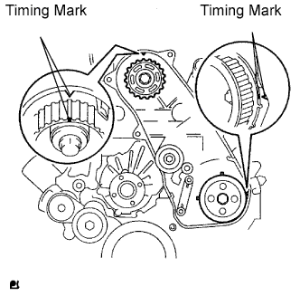 |
Check that the timing marks are aligned as shown in the illustration.
- HINT:
- If reusing the timing belt, align the points marked during removal, and install the belt with the arrow pointing in the direction of engine revolution.
- NOTICE:
- The engine should be cold.
- When turning the crankshaft, the valve heads will hit against the piston's top position. Do not turn it more than necessary.
Using a 10 mm hexagon wrench, install the timing belt idler pulley and new washer with the bolt.
- Torque:
- 35 N*m{357 kgf*cm, 26 ft.*lbf}
Check that the idler pulley moves smoothly.
If it does not move smoothly, check the idler sub-assembly and washer.
Install the timing belt to the pump drive shaft pulley, camshaft timing pulley and No. 1 timing belt idler in sequence.
Place the tensioner upright. Then set a press to the top of the tensioner.
- NOTICE:
- Do not scratch or deform the rod end.
- Press in the tensioner rod upward.
- Protect the tip of the push rod with a cloth in order to prevent damage.
 |
Using the press, slowly push in the push rod using 981 to 9,807 N (100 to 1,000 kgf, 220 to 2,205 lbf) of force.
- NOTICE:
- Do not impose a load of over 9,807 N (100 to 1,000 kgf, 220 to 2,205 lbf) to the push rod.
Align the holes of the push rod and housing. Then pass a 1.5 mm hexagon wrench through the holes to keep the setting position of the push rod.
Install the timing belt tensioner with the 2 bolts while pushing the idler pulley toward the timing belt.
Tighten the 2 bolts.
- Torque:
- 13 N*m{133 kgf*cm, 10 ft.*lbf}
- NOTICE:
- Uniformly tighten the 2 bolts and install the tensioner.
Remove the 1.5 mm hexagon wrench from the tensioner.
 |
Turn the crankshaft clockwise 720° and check that the timing marks are aligned as shown in the illustration.
 |
| 13. INSTALL NO. 1 TIMING BELT COVER |
Install the timing belt cover with the 6 bolts.
- Torque:
- 6.0 N*m{61 kgf*cm, 53 in.*lbf}
Install the wire harness clamp.
Install the water hose clamp with the bolt.
- Torque:
- 18 N*m{184 kgf*cm, 13 ft.*lbf}
| 14. INSTALL EGR VALVE ASSEMBLY |
Install a new gasket and the EGR valve.
| 15. INSTALL NO. 2 NOZZLE LEAKAGE PIPE ASSEMBLY |
Temporarily install the leakage pipe with the 3 bolts.
 |
Temporarily install a new gasket and the check valve.
Fully tighten the 3 bolts and check valve.
- Torque:
- 21 N*m{214 kgf*cm, 16 ft.*lbf} for check valve
- 13 N*m{133 kgf*cm, 10 ft.*lbf} for bolt
Connect the 2 fuel hoses.
| 16. INSTALL INJECTION PIPE |
 |
- NOTICE:
- When replacing the injector, also replace the injection pipe.
- Keep the joints of the injection pipe clean.
Temporarily install the No. 1, No. 2 and No. 3 injection pipes with the union nuts.
Install the No. 2 and No. 3 injection pipe clamps with the bolt and 2 nuts, as shown in the illustration.
- Torque:
- 5.0 N*m{51 kgf*cm, 44 in.*lbf}
- HINT:
- If the painted mark on the No. 1 injection pipe has disappeared, use the illustration as a reference to install the clamps.
Using union nut wrench, tighten the injection pipe union nuts on the common rail side.
- Torque:
- 32 N*m{326 kgf*cm, 24 ft.*lbf} for use with union nut wrench
- 35 N*m{357 kgf*cm, 26 ft.*lbf} for use without union nut wrench
- HINT:
- Use a torque wrench with a fulcrum length of 30 cm (11.81 in.).
 |
Using union nut wrench, tighten the injection pipe union nuts on the injector side.
- Torque:
- 32 N*m{326 kgf*cm, 24 ft.*lbf} for use with union nut wrench
- 35 N*m{357 kgf*cm, 26 ft.*lbf} for use without union nut wrench
- HINT:
- Use a torque wrench with a fulcrum length of 30 cm (11.81 in.).
Temporarily install the No. 4 injection pipe with the union nuts.
 |
Install 2 new injection pipe clamps with the 2 bolts.
- Torque:
- 13 N*m{133 kgf*cm, 10 ft.*lbf}
- NOTICE:
- Make sure that the inner-rubbers of the injection pipe fit inside the clamps.
- When installing the pipe, check that the inner-rubbers and the clamps are in their proper positions.
Using union nut wrench, tighten the injection pipe union nut on the common rail side.
- Torque:
- 32 N*m{326 kgf*cm, 24 ft.*lbf} for use with union nut wrench
- 35 N*m{357 kgf*cm, 26 ft.*lbf} for use without union nut wrench
- HINT:
- Use a torque wrench with a fulcrum length of 30 cm (11.81 in.).
 |
Using union nut wrench, tighten the injection pipe union nut on the injector side.
- Torque:
- 32 N*m{326 kgf*cm, 24 ft.*lbf} for use with union nut wrench
- 35 N*m{357 kgf*cm, 26 ft.*lbf} for use without union nut wrench
- HINT:
- Use a torque wrench with a fulcrum length of 30 cm (11.81 in.).
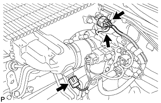
| 17. CONNECT WIRE HARNESS |
| 18. INSTALL MANIFOLD STAY |
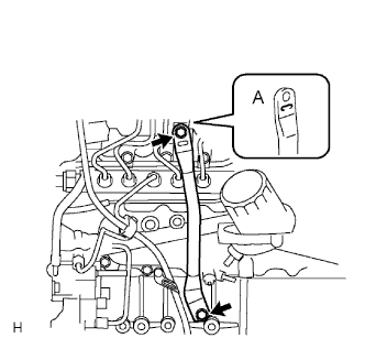 |
Install the stay with the 2 bolts.
- Torque:
- 19 N*m{194 kgf*cm, 14 ft.*lbf}
- HINT:
- The stay's indented area (labeled A) must face the manifold.
| 19. INSTALL EXHAUST MANIFOLD |
 |
Install a new gasket, the exhaust manifold with turbocharger, 4 new collars and 8 spacers to the cylinder head with 8 new nuts.
- Torque:
- 40 N*m{408 kgf*cm, 30 ft.*lbf}
- NOTICE:
- Make sure that the side of the collar with the smaller diameter faces the exhaust manifold.
- Install the collars to the positions labeled A.
| 20. INSTALL NO. 1 COMPRESSOR MOUNTING BRACKET |
Install the bracket with the 4 bolts.
- Torque:
- 47 N*m{479 kgf*cm, 35 ft.*lbf}
| 21. CONNECT COOLER COMPRESSOR ASSEMBLY |
Install the compressor with the 4 bolts.
- Torque:
- 25 N*m{250 kgf*cm, 18 ft.*lbf}
| 22. INSTALL FAN PULLEY |
| 23. INSTALL FAN SHROUD |
Install the fan shroud (Toyota Fortuner RM0000014XZ007X_01_0001.html).
| 24. INSTALL VENTILATION PIPE |
| 25. INSTALL AIR CLEANER ASSEMBLY |
Connect the air cleaner hose.
Install the cleaner with the 2 bolts.
- Torque:
- 14 N*m{143 kgf*cm, 10 ft.*lbf}
Connect the connector to the MAF meter.
Tighten the hose clamp.
| 26. INSTALL CHARGE AIR COOLER ASSEMBLY WITH INTAKE AIR CONNECTOR |
Install the intake air connector to the air hoses.
 |
Install the CAC with the 4 bolts.
- Torque:
- 32 N*m{326 kgf*cm, 24 ft.*lbf}for bolt labeled A
- 12 N*m{125 kgf*cm, 9 ft.*lbf}for bolts labeled B, C and D
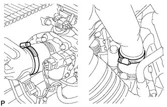
Tighten the 2 clamps.
 |
Connect the vacuum hose to the manifold absolute pressure sensor.
 |
Connect the IAT sensor connector.
Connect the manifold absolute diesel pressure sensor connector.
| 27. INSTALL NO. 1 ENGINE COVER SUB-ASSEMBLY |
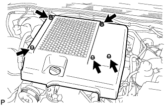 |
Install the engine cover with the 3 bolts and 2 nuts.
- Torque:
- 7.0 N*m{71 kgf*cm, 62 in.*lbf}
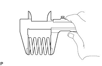
| 28. INSTALL FRONT EXHAUST PIPE ASSEMBLY |
Using a vernier caliper, measure the free length of the compression spring.
- Minimum length:
- 40 mm (1.57 in.)
 |
Install the front pipe to the pipe support.
Install a new gasket to the outlet pipe.
- NOTICE:
- Be careful with the installation direction of the gasket.
- Do not reuse the gasket.
- To ensure a proper seal, do not use the front pipe to force the gasket onto the outlet pipe.
- HINT:
- Using a plastic-faced hammer, uniformly strike the gasket so that the gasket and outlet pipe are properly fit.
 |
Install the front pipe with the 2 compression springs and 2 bolts. Alternately tighten the bolts in several passes.
- Torque:
- 43 N*m{438 kgf*cm, 32 ft.*lbf}
| 29. ADD FUEL |
| 30. TIGHTEN FUEL TANK CAP ASSEMBLY |
| 31. ADD ENGINE OIL |
Wipe the oil pan and drain plug.
Install a new gasket and the drain plug.
- Torque:
- 34 N*m{347 kgf*cm, 25 ft.*lbf}
Add new oil.
- Standard oil capacity:
Item Specified Condition Drain and refill with oil filter change 6.9 liters (7.3 US qts, 6.1 Imp. qts) Drain and refill without oil filter change 6.6 liters (7.0 US qts, 5.8 Imp. qts) Dry fill 7.4 liters (7.8 US qts, 6.5 Imp. qts)
Install the oil filler cap.
| 32. BLEED AIR FROM FUEL SYSTEM |
 |
Using the hand pump, bleed air from the fuel system until pumping becomes difficult.
| 33. CONNECT CABLE TO NEGATIVE BATTERY TERMINAL |
| 34. CHECK FOR ENGINE OIL LEAKS |
| 35. CHECK FOR FUEL LEAKS |
- CAUTION:
- During Active Test mode, engine speed becomes high and combustion noise becomes loud, so pay attention.
- During Active Test mode, fuel becomes high-pressured. Be extremely careful not to expose your eyes, hands, or body to escaped fuel.
Check that there are no leaks from any part of the fuel system when the engine is stopped. If there is fuel leakage, repair or replace parts as necessary.
Start the engine and check that there are no leaks from any part of the fuel system. If there is fuel leakage, repair or replace parts as necessary.
Disconnect the return hose from the common rail.
Start the engine and check for fuel leaks from the return pipe.
If there is fuel leakage, replace the common rail.
Connect the intelligent tester to the DLC3.
Start the engine and push the intelligent tester main switch on.
Select the Fuel Leak test from the Active Test mode on the intelligent tester.
If the intelligent tester is not available, fully depress the accelerator pedal quickly. Increase the engine speed to the maximum and maintain that speed for 2 seconds. Repeat this operation several times.
Check that there are no leaks from any part of the fuel system.
- NOTICE:
- A return pipe leakage of less than 10 cc (0.6 cu in.) per minute is acceptable.
Reconnect the return hose to the common rail.
| 36. CHECK OIL LEVEL |
Warm up the engine, stop the engine and wait for 5 minutes. The oil level should be between the dipstick's low and full level marks.
If the oil level is low, check for leakage and add oil up to the full level mark.- NOTICE:
- Do not add engine oil above the full level mark.