Intake Manifold -- Removal |
- NOTICE:
- When replacing the injectors (including shuffling the injectors between the cylinders), common rail or cylinder head, it is necessary to replace the injection pipes with new ones.
- When replacing the fuel supply pump, common rail, cylinder block, cylinder head, cylinder head gasket or timing gear case, it is necessary to replace the fuel inlet pipe with a new one.
- After removing the injection pipes, clean them with a brush and compressed air.
| 1. DISCONNECT CABLE FROM NEGATIVE BATTERY TERMINAL |
- NOTICE:
- When disconnecting the cable, some systems need to be initialized after the cable is reconnected (Toyota Fortuner RM000004W63000X.html).
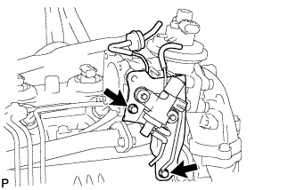
| 2. REMOVE MANIFOLD STAY WITH VACUUM SWITCHING VALVE |
Disconnect the vacuum switching valve connector.
 |
Disconnect the 3 vacuum transmitting hoses.
 |
Remove the 2 bolts and manifold stay with vacuum switching valve.
 |
| 3. REMOVE ENGINE OIL LEVEL DIPSTICK GUIDE |
Remove the engine oil level dipstick.
Remove the bolt and injection pipe clamp.
 |
Remove the bolt and engine oil level dipstick guide.
Remove the O-ring from the engine oil level dipstick guide.
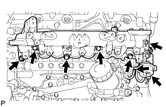
| 4. REMOVE NO. 1, NO. 2 AND NO. 3 INJECTION PIPE SUB-ASSEMBLY |
- NOTICE:
- After removing the fuel pipe, cover the outlets on the common rail with tape to keep out foreign matter.
- After removing the fuel pipe, put it in a plastic bag to prevent foreign matter from contaminating its injector inlet.
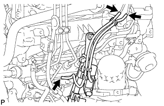
Remove the 2 nuts and No. 3 injection pipe clamp.
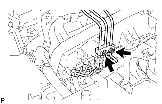 |
Remove the 2 bolts and 2 No. 2 injection pipe clamps.
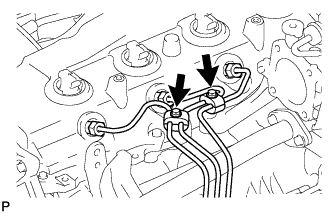 |
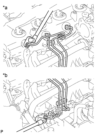
Using a 17 mm union nut wrench, loosen the union nuts and remove the No. 1, No. 2 and No. 3 injection pipes.
Text in Illustration *a Injector Side *b Common Rail Side
 |
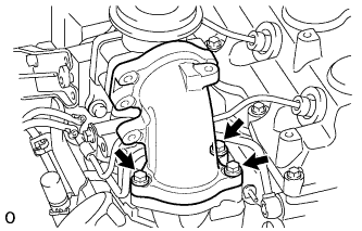
| 5. REMOVE NO. 2 INTAKE AIR CONNECTOR BRACKET |
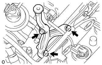
Remove the 3 bolts and No. 2 intake air connector bracket.
 |
| 6. DISCONNECT NO. 3 WATER BY-PASS PIPE |
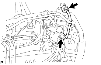
Remove the 2 bolts and disconnect the No. 3 water by-pass pipe with the wire harness.
 |
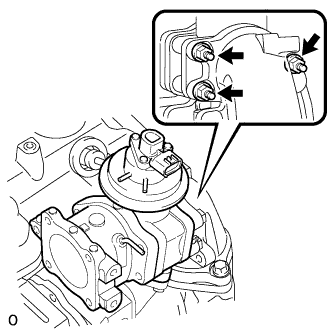
| 7. REMOVE ELECTRIC VACUUM REGULATING VALVE ASSEMBLY (for EGR) |
Disconnect the 2 connectors.
 |
Disconnect the 6 vacuum hoses.
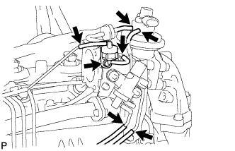 |
Remove the bolt and No. 1 gas filter with gas filter bracket.
Remove the 2 bolts and electric vacuum regulating valve.
 |
| 8. REMOVE NO. 2 INTAKE AIR CONNECTOR |
Remove the 3 nuts, No. 2 intake air connector and gasket.
 |
| 9. REMOVE INTAKE AIR CONNECTOR |
Remove the 3 bolts, intake air connector and 2 gaskets.
 |
| 10. REMOVE ELECTRIC EGR CONTROL VALVE ASSEMBLY |
| 11. REMOVE NO. 4 INJECTION PIPE SUB-ASSEMBLY |
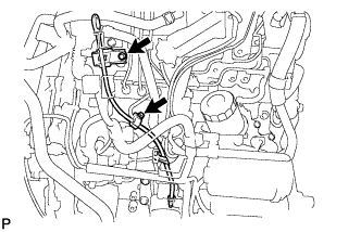
Remove the bolt and disconnect the injection pipe clamp.
- NOTICE:
- If an injection pipe clamp is removed from the No. 4 injection pipe, replace the injection clamp with a new one.
 |
Using a 17 mm union nut wrench, loosen the union nuts and remove the No. 4 injection pipe.
Text in Illustration *a Injector Side *b Common Rail Side
 |
| 12. REMOVE NO. 2 NOZZLE LEAKAGE PIPE ASSEMBLY |
Disconnect the 3 fuel hoses.
Remove the union bolt, 3 bolts, No. 2 nozzle leakage pipe and gasket.
Text in Illustration *1 Union Bolt
 |
| 13. REMOVE NO. 3 INTERCOOLER SUPPORT BRACKET |
Remove the bolt and No. 3 intercooler support bracket.
 |
| 14. REMOVE INTAKE MANIFOLD INSULATOR |
Remove the 2 bolts and intake manifold insulator from the intake manifold.
 |
| 15. REMOVE INTAKE MANIFOLD |
Disconnect the vacuum hose and vacuum switching valve connector.
 |
Remove the 4 bolts, 2 nuts, intake manifold and gasket.