Clutch Unit (For 2Tr-Fe) Removal
REMOVE MANUAL TRANSMISSION UNIT ASSEMBLY
REMOVE CLUTCH RELEASE BEARING ASSEMBLY
REMOVE CLUTCH RELEASE FORK BOOT
REMOVE CLUTCH RELEASE FORK SUB-ASSEMBLY
REMOVE RELEASE BEARING HUB CLIP
REMOVE RELEASE FORK SUPPORT
REMOVE CLUTCH COVER ASSEMBLY
REMOVE CLUTCH DISC ASSEMBLY
INSPECT INPUT SHAFT FRONT BEARING
REMOVE INPUT SHAFT FRONT BEARING
INSPECT CLUTCH DISC ASSEMBLY
INSPECT CLUTCH COVER ASSEMBLY
INSPECT FLYWHEEL SUB-ASSEMBLY
INSPECT CLUTCH RELEASE BEARING ASSEMBLY
Clutch Unit (For 2Tr-Fe) -- Removal |
| 1. REMOVE MANUAL TRANSMISSION UNIT ASSEMBLY |
Remove the manual transmission unit (Toyota Fortuner RM0000011AL006X.html).
| 2. REMOVE CLUTCH RELEASE BEARING ASSEMBLY |
| 3. REMOVE CLUTCH RELEASE FORK BOOT |
| 4. REMOVE CLUTCH RELEASE FORK SUB-ASSEMBLY |
| 5. REMOVE RELEASE BEARING HUB CLIP |
| 6. REMOVE RELEASE FORK SUPPORT |
Remove the release fork support from the manual transmission unit.
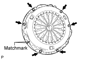
| 7. REMOVE CLUTCH COVER ASSEMBLY |
Place matchmarks on the clutch cover and flywheel.
Loosen each set bolt one turn at a time until spring tension is released.
Remove the 6 set bolts and pull off the clutch cover.
- NOTICE:
- Do not drop the clutch disc.
| 8. REMOVE CLUTCH DISC ASSEMBLY |
- NOTICE:
- Keep the lining part of the clutch disc, pressure plate and surface of the flywheel away from oil and foreign matter.
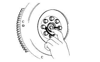
| 9. INSPECT INPUT SHAFT FRONT BEARING |
Turn the bearing by hand by applying rotational force.
If the bearing sticks or has much resistance, replace the input shaft bearing.
- HINT:
- The bearing is permanently lubricated and requires no cleaning or lubrication.
| 10. REMOVE INPUT SHAFT FRONT BEARING |
Remove any 2 diametrically opposite bolts.
Using SST, remove the input shaft bearing.
- SST
- 09303-35011
| 11. INSPECT CLUTCH DISC ASSEMBLY |
Using a vernier caliper, measure the rivet head depth.
- Minimum rivet depth:
- 0.3 mm (0.012 in)
If the depth is less than the minimum, replace the clutch disc assembly.
Install the clutch disc to the transmission unit.
- NOTICE:
- Be careful not to insert the clutch disc facing the wrong direction.
Using a dial indicator, check the disc runout.
- Maximum runout:
- 0.8 mm (0.031 in.)
If the runout is greater than the maximum, replace the clutch disc assembly.
| 12. INSPECT CLUTCH COVER ASSEMBLY |
Using a vernier caliper, measure the depth and width of the worn areas of the diaphragm spring.
- Maximum:
Measurement
| Maximum
|
A (Depth)
| 0.5 mm (0.020 in.)
|
B (Width)
| 6.0 mm (0.236 in.)
|
If the depth or width is greater than the maximum, replace the clutch cover assembly.
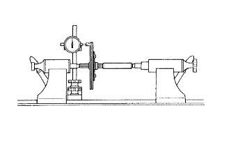
| 13. INSPECT FLYWHEEL SUB-ASSEMBLY |
Using a dial indicator, measure the flywheel runout.
- Maximum runout:
- 0.1 mm (0.004 in.)
If the runout is greater than the maximum, replace the flywheel sub-assembly.
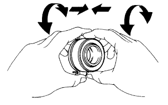
| 14. INSPECT CLUTCH RELEASE BEARING ASSEMBLY |
Turn the bearing by hand while applying force in the axial direction.
If the bearing sticks or has much resistance, replace the release bearing.
- HINT:
- The bearing is permanently lubricated and requires no cleaning or lubrication.