Camshaft -- Inspection |
| 1. INSPECT VALVE LASH ADJUSTER |
 |
- NOTICE:
- Keep the lash adjuster free from foreign matter.
- Only use clean engine oil.
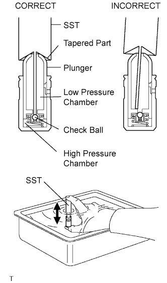
Place the lash adjuster into a container full of engine oil.
Insert SST's tip into the lash adjuster's plunger and use the tip to press down on the check ball inside the plunger.
- SST
- 09276-75010
Squeeze SST and lash adjuster together to move the plunger up and down 5 to 6 times.
Check the movement of the plunger and bleed air.
- OK:
- Plunger moves up and down.
- NOTICE:
- When bleeding high-pressure air from the compression chamber, make sure that the tip of SST is actually pressing the check ball as shown in the illustration. If the check ball is not pressed, air will not bleed.
After bleeding air, remove SST. Then, try to quickly and firmly press the plunger with a finger.
- OK:
- Plunger is difficult to move.
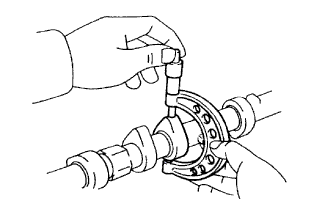
| 2. INSPECT CAMSHAFT TIMING GEAR |
Check the lock of the camshaft timing gear.
Clamp the camshaft in a vise, and confirm that the camshaft timing gear is locked.
- NOTICE:
- Be careful not to damage the camshaft.
 |
Release the lock pin.
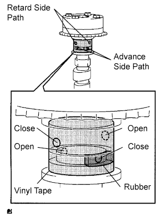
Cover the 4 oil paths of the cam journal with vinyl tape as shown in the illustration.
- HINT:
- 2 advance side paths are provided in the groove of the camshaft. Plug one of the paths with a piece of rubber.
Break through the tape of the advance side path and the retard side path on the opposite side of the groove.
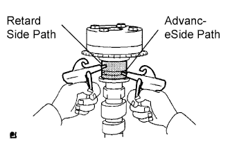
Apply approximately 200 kPa (2.0 kgf/cm2, 28 psi) of air pressure to the paths whose tape was broken in the procedure above.
- CAUTION:
- Some oil spraying will occur. Contain the spray with a cloth.
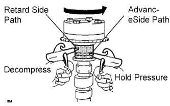
Check that the camshaft timing gear revolves in the advance direction when weakening the air pressure of the retard side path.
- OK:
- Gear rotates in advance direction.
- HINT:
- This operation releases the lock pin for the extreme retard position.
When the camshaft timing gear reaches the extreme advance position, remove the air gun from the retard side path and advance side path, in that order.
- NOTICE:
- Do not remove the air gun from the advance side path first. The gear may abruptly shift in the retard direction and break the lock pin.
Check for smooth rotation.
Rotate the camshaft timing gear within its movable range several times, but do not turn it to the extreme retard position. Check that the gear rotates smoothly.
- OK:
- Gear rotates smoothly.
- NOTICE:
- Do not use an air gun to perform the smooth operation check.
Check the lock in the extreme retard position.
Confirm that the camshaft timing gear is locked at the extreme retard position.
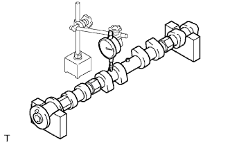
| 3. INSPECT NO. 1 CAMSHAFT |
Check the camshaft for runout.
Place the camshaft on V-blocks.
Using a dial indicator, measure the circle runout at the center journal.
- Maximum circle runout:
- 0.03 mm (0.0012 in.)
 |
Using a micrometer, measure the cam lobe height.
- Standard cam lobe height:
- 42.855 to 42.955 mm (1.6872 to 1.6911 in.)
- Minimum cam lobe height:
- 42.855 mm (1.6872 in.)
 |
Using a micrometer, measure the journal diameter.
- Standard journal diameter:
Item Specified Condition No. 1 journal 35.949 to 35.965 mm (1.4153 to 1.4159 in.) Other journal 26.959 to 26.975 mm (1.0614 to 1.0620 in.)
 |
| 4. INSPECT NO. 2 CAMSHAFT |
Check the camshaft for runout.
Place the camshaft on V-blocks.
Using a dial indicator, measure the circle runout at the center journal.
- Maximum circle runout:
- 0.03 mm (0.0012 in.)
 |
Using a micrometer, measure the cam lobe height.
- Standard cam lobe height:
- 42.854 to 42.954 mm (1.687 to 1.6911 in.)
- Minimum cam lobe height:
- 42.854 mm (1.6872 in.)
 |
Using a micrometer, measure the journal diameter.
- Standard journal diameter:
Item Specified Condition No. 1 journal 35.949 to 35.965 mm (1.4153 to 1.4159 in.) Other journal 26.959 to 26.975 mm (1.0614 to 1.0620 in.)
|