Compressor And Magnetic Clutch (For 5L-E) -- Installation |
| 1. ADJUST COMPRESSOR OIL |
When replacing the compressor and magnet clutch with a new one, gradually discharge the refrigerant gas from the service valve, and drain the following amount of oil from the new compressor and magnet clutch before installation.
- Standard:
- (Oil capacity inside the new compressor and magnet clutch: 180 + 15 cc (6.08 + 0.51 fl.oz.)) - (Remaining oil amount in the removed compressor and magnet clutch) = (Oil amount to be removed from the new compressor)
- NOTICE:
- When checking the compressor oil level, follow the A/C system precautions.
- If a new compressor and magnet clutch is installed without removing the oil remaining in the pipes of the vehicle, the oil amount will be too large. This prevents heat exchange in the refrigerant cycle and causes refrigerant failure.
- If the volume of oil remaining in the removed compressor and magnet clutch is small, check for oil leakage.
- Be sure to use ND-OIL 8 or equivalent compressor oil.
| 2. INSTALL COOLER COMPRESSOR ASSEMBLY |
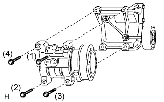 |
Install the compressor with the 4 bolts and tighten the bolts in the order shown in the illustration.
- Torque:
- 24.5 N*m{250 kgf*cm, 18 ft.*lbf}
Connect the connector.
| 3. INSTALL NO. 1 COOLER REFRIGERANT DISCHARGE HOSE |
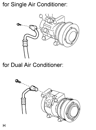 |
Remove the vinyl tape attached to the hose.
Sufficiently apply compressor oil to a new O-ring and the fitting surface of the compressor.
- Compressor oil:
- ND-OIL 8 or equivalent
Install the O-ring to the discharge hose.
Connect the discharge hose with the bolt.
- Torque:
- 9.8 N*m{100 kgf*cm, 7 ft.*lbf}
| 4. INSTALL SUCTION HOSE SUB-ASSEMBLY |
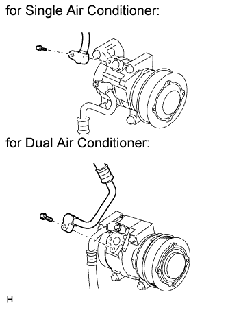 |
Remove the vinyl tape attached to the hose.
Sufficiently apply compressor oil to a new O-ring and the fitting surface of the compressor.
- Compressor oil:
- ND-OIL 8 or equivalent
Install the O-ring to the suction hose.
Connect the suction hose with the bolt.
- Torque:
- 9.8 N*m{100 kgf*cm, 7 ft.*lbf}
| 5. INSTALL DRIVE BELT |
Install the V belt.
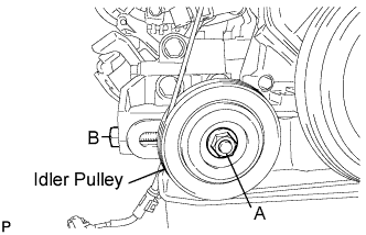 |
Tightening bolt B, adjust the deflection of the V belt (Toyota Fortuner RM000001KYZ001X_01_0001.html).
Tighten nut A.
- Torque:
- 39 N*m{400 kgf*cm, 29 ft.*lbf}
Recheck the deflection of the V belt.
| 6. INSTALL AIR CLEANER ASSEMBLY |
Install the cleaner with the 2 bolts.
- Torque:
- 14 N*m{143 kgf*cm, 10 ft.*lbf}
Connect the connector to the IAT sensor.
Connect the hose clamp.
| 7. CONNECT CABLE TO NEGATIVE BATTERY TERMINAL |
- NOTICE:
- When disconnecting the cable, some systems need to be initialized after the cable is reconnected (Toyota Fortuner RM000002HD2006X.html).
| 8. CHARGE REFRIGERANT |
- SST
- 09985-20010(09985-02130,09985-02150,09985-02090,09985-02110,09985-02010,09985-02050,09985-02060,09985-02070)
Perform vacuum purging using a vacuum pump.
Charge refrigerant HFC-134a (R134a).
- Standard:
- 750 +-30 g (26.45 +-1.05 oz.)
- NOTICE:
- Do not operate the cooler compressor before charging refrigerant as the cooler compressor will not work properly without any refrigerant, and will overheat.
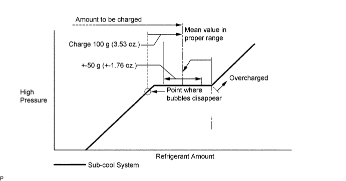
- Approximately 100 g (3.53 oz.) of refrigerant may need to be charged after bubbles disappear. The refrigerant amount should be checked by quantity, and not with the sight glass.
| 9. WARM UP ENGINE |
Warm up the engine at less than 1,850 rpm for 2 minutes or more after charging refrigerant.
- NOTICE:
- Be sure to warm up the compressor when turning the A/C switch ON after removing and installing the cooler refrigerant lines (including the compressor), to prevent damage to the compressor.
| 10. CHECK FOR LEAKAGE OF REFRIGERANT |
After recharging the refrigerant gas, check for refrigerant gas leakage using a halogen leak detector.
After recharging the refrigerant gas, prepare the vehicle for a refrigerant gas leakage check by making sure the following conditions are met.
The ignition switch is OFF.
The vehicle is in a place with good air ventilation and without any volatile gases, such as evaporated gasoline or exhaust gas. The detector is very sensitive gases, If volatile gases are unavoidable, the vehicle must be lifted up.
Some refrigerant is remaining in the refrigerant system.
The compressor is OFF and its pressure is approximately 392 to 588 kPa (4 to 6 kgf/cm2).
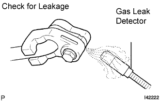
Using a gas leak detector, check the refrigerant line for leakage.
 |
If a gas leak is not detected on the drain hose, remove the blower motor control (blower resistor) from the cooling unit. Insert the gas leak detector sensor into the unit and perform the test.
Disconnect the connector and leave the pressure switch on for approximately 20 minutes. Bring the gas leak detector close to the pressure switch and perform the test.