Meter / Gauge System Entire Combination Meter Does Not Operate
DESCRIPTION
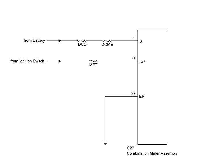
WIRING DIAGRAM
INSPECTION PROCEDURE
CHECK HARNESS AND CONNECTOR (COMBINATION METER ASSEMBLY - BATTERY AND BODY GROUND)
METER / GAUGE SYSTEM - Entire Combination Meter does not Operate |
DESCRIPTION
This circuit is the power source circuit for the meter.
WIRING DIAGRAM
INSPECTION PROCEDURE
- NOTICE:
- Inspect the fuses for circuits related to this system before performing the following inspection procedure.
| 1.CHECK HARNESS AND CONNECTOR (COMBINATION METER ASSEMBLY - BATTERY AND BODY GROUND) |
Disconnect the C27 combination meter assembly connector.
Measure the resistance according to the value(s) in the table below.
- Standard Resistance:
Tester Connection
| Condition
| Specified Condition
|
C27-22 (EP) - Body ground
| Always
| Below 1 Ω
|
Measure the voltage according to the value(s) in the table below.
- Standard Voltage:
Tester Connection
| Condition
| Specified Condition
|
C27-1 (B) - Body ground
| Always
| 11 to 14 V
|
C27-21 (IG+) - Body ground
| Ignition switch ON
| 11 to 14 V
|
C27-21 (IG+) - Body ground
| Ignition switch off
| Below 1 V
|
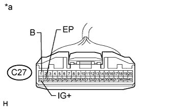
Text in Illustration*a
| Front view of wire harness connector
(to Combination Meter Assembly)
|
| | REPAIR OR REPLACE HARNESS OR CONNECTOR |
|
|