DESCRIPTION
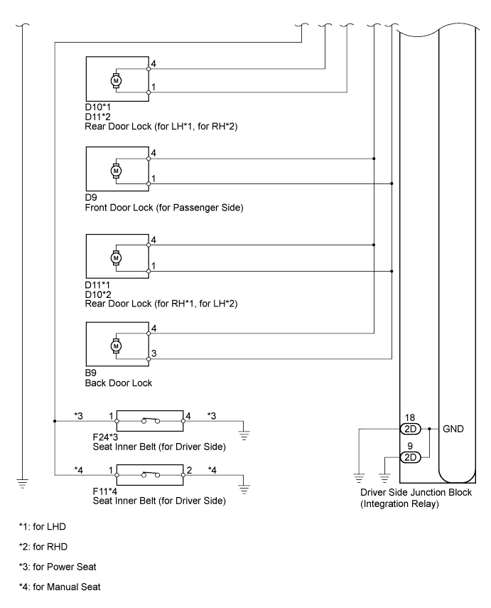
WIRING DIAGRAM
INSPECTION PROCEDURE
CHECK DOOR LOCK / UNLOCK OPERATION
INSPECT POWER WINDOW REGULATOR MASTER SWITCH ASSEMBLY (DOOR CONTROL SWITCH)
CHECK WIRE HARNESS (MASTER SWITCH - INTEGRATION RELAY AND BODY GROUND)
INSPECT FRONT DOOR LOCK (FOR DRIVER SIDE (DOOR LOCK AND UNLOCK SWITCH))
INSPECT FRONT SEAT INNER BELT ASSEMBLY (for Driver Side)
CHECK WIRE HARNESS (DOOR LOCK FOR DRIVER SIDE - INTEGRATION RELAY AND BODY GROUND)
INSPECT DOOR LOCK ASSEMBLY (for Driver Side, Passenger Side, Rear LH, Rear RH, Back Door)
CHECK WIRE HARNESS (DOOR LOCK - INTEGRATION RELAY AND BODY GROUND)
INSPECT FUSE (ECU-B, DCC, DOOR)
CHECK WIRE HARNESS (INTEGRATION RELAY - BATTERY AND BODY GROUND)
CHECK WIRE HARNESS (MASTER SWITCH - INTEGRATION RELAY AND BODY GROUND)
POWER DOOR LOCK CONTROL SYSTEM (w/o Theft Deterrent System) - All Doors cannot be Locked / Unlocked Simultaneously |
DESCRIPTION
The integration relay drives the door lock motors according to switch signals from the door control switch of the power window regulator master switch and the driver side door key cylinder.However, the driver side door key-linked lock / unlock function will not operate when the seat belt is fastened.
WIRING DIAGRAM
INSPECTION PROCEDURE
| 1.CHECK DOOR LOCK / UNLOCK OPERATION |
Proceed to the next step according to the symptom listed in the table below.
Symptom
| Proceed to
|
All doors cannot be locked / unlocked at once using door control switch on master switch (switch operation)
| A
|
All doors cannot be locked / unlocked at once using door key cylinder on driver side (key operation)
| B
|
Only one door cannot be locked / unlocked
| C
|
All symptoms listed above are present
| D
|
| 2.INSPECT POWER WINDOW REGULATOR MASTER SWITCH ASSEMBLY (DOOR CONTROL SWITCH) |
Remove the power window regulator master switch (Toyota Fortuner RM00000138V003X_02_0005.html).
Measure the resistance of the door control switch.
- Standard resistance:
w/o Jam Protection FunctionTester Connection
| Switch Condition
| Specified Condition
|
5 - 3
| Lock
| Below 1 Ω
|
5 - 3, 8- 3
| OFF
| 10 kΩ or higher
|
8 - 3
| Unlock
| Below 1 Ω
|
w/ Jam Protection FunctionTester Connection
| Switch Condition
| Specified Condition
|
5 - 1
| Lock
| Below 1 Ω
|
5 - 1, 8- 1
| OFF
| 10 kΩ or higher
|
8 - 1
| Unlock
| Below 1 Ω
|
| | REPLACE POWER WINDOW REGULATOR MASTER SWITCH ASSEMBLY |
|
|
| 3.CHECK WIRE HARNESS (MASTER SWITCH - INTEGRATION RELAY AND BODY GROUND) |
Disconnect the P6 switch connector.
Disconnect the 2A and 2D integration relay connectors.
Measure the resistance of the wire harness side connectors.
- Standard resistance:
w/o Jam Protection FunctionTester Connection
| Specified Condition
|
P6-5 - 2A-4 (L1)
| Below 1 Ω
|
P6-8 - 2D-4 (UL1)
| Below 1 Ω
|
P6-3 - Body ground
| Below 1 Ω
|
P6-5 or 2A-4 (L1) - Body ground
| 10 kΩ or higher
|
P6-8 or 2D-4 (UL1) - Body ground
| 10 kΩ or higher
|
w/ Jam Protection FunctionTester Connection
| Specified Condition
|
P6-5 - 2A-4 (L1)
| Below 1 Ω
|
P6-8 - 2D-4 (UL1)
| Below 1 Ω
|
P6-1 - Body ground
| Below 1 Ω
|
P6-5 or 2A-4 (L1) - Body ground
| 10 kΩ or higher
|
P6-8 or 2D-4 (UL1) - Body ground
| 10 kΩ or higher
|
| | REPAIR OR REPLACE HARNESS OR CONNECTOR |
|
|
| OK |
|
|
|
| REPLACE DRIVER SIDE JUNCTION BLOCK ASSEMBLY |
|
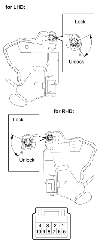
| 4.INSPECT FRONT DOOR LOCK (FOR DRIVER SIDE (DOOR LOCK AND UNLOCK SWITCH)) |
w/ Wireless Door Lock Control System:
Remove the front door lock. For the front driver side, refer to the following procedures (Toyota Fortuner RM00000138V003X.html).
Measure the resistance of the door lock and unlock switch.
- Standard resistance:
for LHDTester Connection
| Door Lock Condition
| Specified Condition
|
9 - 7
| Lock
| Below 1 Ω
|
9 - 7, 10 - 7
| OFF
| 10 kΩ or higher
|
10 - 7
| Unlock
| Below 1 Ω
|
- for RHD:
Tester Connection
| Door Lock Condition
| Specified Condition
|
6 - 8
| Lock
| Below 1 Ω
|
5 - 8, 6 - 8
| OFF
| 10 kΩ or higher
|
5 - 8
| Unlock
| Below 1 Ω
|
Measure the resistance of the detection switch.
- Standard resistance:
for LHDTester Connection
| Door Lock Condition
| Specified Condition
|
8 - 7
| Lock
| 10 kΩ or higher
|
8 - 7
| Unlock
| Below 1 Ω
|
- for RHD:
Tester Connection
| Door Lock Condition
| Specified Condition
|
7 - 8
| Lock
| 10 kΩ or higher
|
7 - 8
| Unlock
| Below 1 Ω
|
w/o Wireless Door Lock Control System:
Remove the front door lock. For the front driver side, refer to the following procedures (Toyota Fortuner RM00000138V003X.html).
Measure the resistance of the door lock and unlock switch.
- Standard resistance:
for LHDTester Connection
| Door Lock Condition
| Specified Condition
|
9 - 7
| Lock
| Below 1 Ω
|
9 - 7, 10 - 7
| OFF
| 10 kΩ or higher
|
10 - 7
| Unlock
| Below 1 Ω
|
- for RHD:
Tester Connection
| Door Lock Condition
| Specified Condition
|
6 - 8
| Lock
| Below 1 Ω
|
5 - 8, 6 - 8
| OFF
| 10 kΩ or higher
|
5 - 8
| Unlock
| Below 1 Ω
|
| | REPLACE FRONT DOOR LOCK ASSEMBLY (for Driver Side) |
|
|
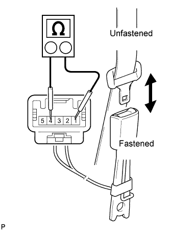
| 5.INSPECT FRONT SEAT INNER BELT ASSEMBLY (for Driver Side) |
for Power Seat:
Remove the front seat inner belt. For the front driver side, refer to the following procedures (Toyota Fortuner RM00000122H01XX.html).
Measure the resistance of the buckle switch.
- Standard resistance:
Tester Connection
| Switch Condition
| Specified Condition
|
1 - 4
| Seat belt is unfastened
| Below 1 Ω
|
1 - 4
| Seat belt is fastened
| 1 MΩ or higher
|
for Manual Seat:
Remove the front seat inner belt. For the front driver side, refer to the following procedures (Toyota Fortuner RM00000122H00BX.html).
Measure the resistance of the buckle switch.
- Standard resistance:
Tester Connection
| Switch Condition
| Specified Condition
|
1 - 2
| Seat belt is unfastened
| Below 1 Ω
|
1 - 2
| Seat belt is fastened
| 1 MΩ or higher
|
| | REPLACE FRONT SEAT INNER BELT ASSEMBLY (for Driver Side) |
|
|
| 6.CHECK WIRE HARNESS (DOOR LOCK FOR DRIVER SIDE - INTEGRATION RELAY AND BODY GROUND) |
Disconnect the D8 door lock connector.
Disconnect the 2A and 2D integration relay connectors.
Measure the resistance of the wire harness side connectors.
- Standard resistance:
for LHDTester Connection
| Condition
| Specified Condition
|
D8-10 - 2D-4 (UL1)
| Always
| Below 1 Ω
|
D8-9 - 2A-4 (L1)
| Always
| Below 1 Ω
|
D8-7 - Body ground
| Driver seat belt is unfastened
| Below 1 Ω
|
D8-8 - 2D-7 (LSWD)*
| Always
| Below 1 Ω
|
D8-10 or 2D-4 (UL1) - Body ground
| Always
| 10 kΩ or higher
|
D8-9 or 2A-4 (L1) - Body ground
| Always
| 10 kΩ or higher
|
D8-8 or 2D-7 (LSWD) - Body ground*
| Always
| 10 kΩ or higher
|
- for RHD:
Tester Connection
| Condition
| Specified Condition
|
D8-5 - 2D-4 (UL1)
| Always
| Below 1 Ω
|
D8-6 - 2A-4 (L1)
| Always
| Below 1 Ω
|
D8-8 - Body ground
| Driver seat belt is unfastened
| Below 1 Ω
|
D8-7 - 2D-7 (LSWD)*
| Always
| Below 1 Ω
|
D8-5 or 2D-4 (UL1) - Body ground
| Always
| 10 kΩ or higher
|
D8-6 or 2A-4 (L1) - Body ground
| Always
| 10 kΩ or higher
|
D8-7 or 2D-7 (LSWD) - Body ground*
| Always
| 10 kΩ or higher
|
- HINT:
- *: w/ Wireless Door Lock Control System
| | REPAIR OR REPLACE HARNESS OR CONNECTOR |
|
|
| OK |
|
|
|
| REPLACE DRIVER SIDE JUNCTION BLOCK ASSEMBLY |
|
| 7.INSPECT DOOR LOCK ASSEMBLY (for Driver Side, Passenger Side, Rear LH, Rear RH, Back Door) |
Remove the door lock. For the front door lock, refer to the following procedures (Toyota Fortuner RM00000138V003X.html). For the rear door lock, refer to the following procedures (Toyota Fortuner RM00000138Z003X.html). For the back door lock, refer to the following procedures (Toyota Fortuner RM000001J95002X.html).
Apply battery voltage to the door lock and check the operation of the door lock motor.
- OK:
for Driver side, Passenger side, Rear LH, Rear RHMeasurement Condition
| Specified Condition
|
Battery positive (+) → Terminal 4
Battery negative (-) → Terminal 1
| Lock
|
Battery positive (+) → Terminal 1
Battery negative (-) → Terminal 4
| Unlock
|
for Back doorMeasurement Condition
| Specified Condition
|
Battery positive (+) → Terminal 4
Battery negative (-) → Terminal 3
| Lock
|
Battery positive (+) → Terminal 3
Battery negative (-) → Terminal 4
| Unlock
|
| | REPLACE DOOR LOCK ASSEMBLY |
|
|
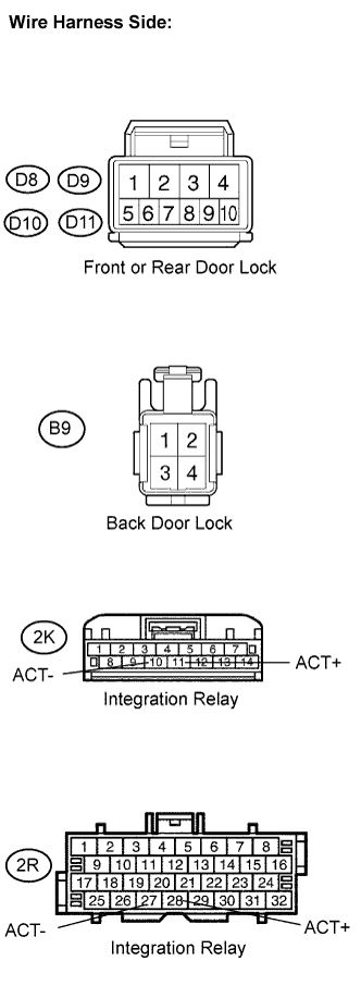
| 8.CHECK WIRE HARNESS (DOOR LOCK - INTEGRATION RELAY AND BODY GROUND) |
Disconnect the D8, D9, D10 and D11 door lock connectors.
Disconnect the B9 back door lock connector.
Disconnect the 2K and 2R integration relay connectors.
Measure the resistance of the wire harness side connectors.
- Standard resistance:
for LHDTester Connection
| Specified Condition
|
D8-4 - 2R-28 (ACT+)
| Below 1 Ω
|
D8-1 - 2R-27 (ACT-)
| Below 1 Ω
|
D9-4 - 2K-11 (ACT+)
| Below 1 Ω
|
D9-1 - 2K-10 (ACT-)
| Below 1 Ω
|
D10-4 - 2R-28 (ACT+)
| Below 1 Ω
|
D10-1 - 2R-27 (ACT-)
| Below 1 Ω
|
D11-4 - 2K-11 (ACT+)
| Below 1 Ω
|
D11-1 - 2K-10 (ACT-)
| Below 1 Ω
|
B9-4 - 2K-11 (ACT+)
| Below 1 Ω
|
B9-3 - 2K-10 (ACT-)
| Below 1 Ω
|
D8-4 or 2R-28 (ACT+) - Body ground
| 10 kΩ or higher
|
D8-1 or 2R-27 (ACT-) - Body ground
| 10 kΩ or higher
|
D9-4 or 2K-11 (ACT+) - Body ground
| 10 kΩ or higher
|
D9-1 or 2K-10 (ACT-) - Body ground
| 10 kΩ or higher
|
D10-4 or 2R-28 (ACT+) - Body ground
| 10 kΩ or higher
|
D10-1 or 2R-27 (ACT-) - Body ground
| 10 kΩ or higher
|
D11-4 or 2K-11 (ACT+) - Body ground
| 10 kΩ or higher
|
D11-1 or 2K-10 (ACT-) - Body ground
| 10 kΩ or higher
|
B9-4 or 2K-11 (ACT+) - Body ground
| 10 kΩ or higher
|
B9-3 or 2K-10 (ACT-) - Body ground
| 10 kΩ or higher
|
- for RHD:
Tester Connection
| Specified Condition
|
D8-4 - 2R-28 (ACT+)
| Below 1 Ω
|
D8-1 - 2R-27 (ACT-)
| Below 1 Ω
|
D9-4 - 2K-11 (ACT+)
| Below 1 Ω
|
D9-1 - 2K-10 (ACT-)
| Below 1 Ω
|
D10-4 - 2K-11 (ACT+)
| Below 1 Ω
|
D10-1 - 2K-10 (ACT-)
| Below 1 Ω
|
D11-4 - 2R-28 (ACT+)
| Below 1 Ω
|
D11-1 - 2R-27 (ACT-)
| Below 1 Ω
|
B9-4 - 2K-11 (ACT+)
| Below 1 Ω
|
B9-3 - 2K-10 (ACT-)
| Below 1 Ω
|
D8-4 or 2R-28 (ACT+) - Body ground
| 10 kΩ or higher
|
D8-1 or 2R-27 (ACT-) - Body ground
| 10 kΩ or higher
|
D9-4 or 2K-11 (ACT+) - Body ground
| 10 kΩ or higher
|
D9-1 or 2K-10 (ACT-) - Body ground
| 10 kΩ or higher
|
D10-4 or 2K-11 (ACT+) - Body ground
| 10 kΩ or higher
|
D10-1 or 2K-10 (ACT-) - Body ground
| 10 kΩ or higher
|
D11-4 or 2R-28 (ACT+) - Body ground
| 10 kΩ or higher
|
D11-1 or 2R-27 (ACT-) - Body ground
| 10 kΩ or higher
|
B9-4 or 2K-11 (ACT+) - Body ground
| 10 kΩ or higher
|
B9-3 or 2K-10 (ACT-) - Body ground
| 10 kΩ or higher
|
| | REPAIR OR REPLACE HARNESS OR CONNECTOR |
|
|
| OK |
|
|
|
| REPLACE DRIVER SIDE JUNCTION BLOCK ASSEMBLY |
|
| 9.INSPECT FUSE (ECU-B, DCC, DOOR) |
Remove the ECU-B and DCC fuses from the engine room relay block.
Remove the DOOR fuse from the No. 3 relay block.
Measure the resistance of the fuses.
- Standard resistance:
- Below 1 Ω
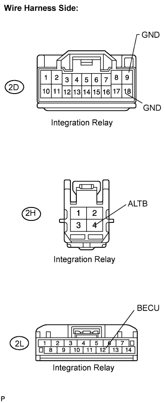
| 10.CHECK WIRE HARNESS (INTEGRATION RELAY - BATTERY AND BODY GROUND) |
Disconnect the 2D, 2H and 2L integration relay connectors.
Measure the voltage and resistance of the wire harness side connectors.
- Standard voltage:
Tester Connection
| Specified Condition
|
2L-12 (BECU) - Body ground
| 11 to 14 V
|
2H-4 (ALTB) - Body ground
| 11 to 14 V
|
- Standard resistance:
Tester Connection
| Specified Condition
|
2D-9 (GND) - Body ground
| Below 1 Ω
|
2D-18 (GND) - Body ground
| Below 1 Ω
|
| | REPAIR OR REPLACE HARNESS OR CONNECTOR |
|
|
| 11.CHECK WIRE HARNESS (MASTER SWITCH - INTEGRATION RELAY AND BODY GROUND) |
Disconnect the P6 switch connector.
Disconnect the 2A and 2D integration relay connectors.
Measure the resistance of the wire harness side connectors.
- Standard resistance:
w/o Jam Protection FunctionTester Connection
| Specified Condition
|
P6-5 - 2A-4 (L1)
| Below 1 Ω
|
P6-8 - 2D-4 (UL1)
| Below 1 Ω
|
P6-3 - Body ground
| Below 1 Ω
|
P6-5 or 2A-4 (L1) - Body ground
| 10 kΩ or higher
|
P6-8 or 2D-4 (UL1) - Body ground
| 10 kΩ or higher
|
w/ Jam Protection FunctionTester Connection
| Specified Condition
|
P6-5 - 2A-4 (L1)
| Below 1 Ω
|
P6-8 - 2D-4 (UL1)
| Below 1 Ω
|
P6-1 - Body ground
| Below 1 Ω
|
P6-5 or 2A-4 (L1) - Body ground
| 10 kΩ or higher
|
P6-8 or 2D-4 (UL1) - Body ground
| 10 kΩ or higher
|
| | REPAIR OR REPLACE HARNESS OR CONNECTOR |
|
|
| OK |
|
|
|
| REPLACE DRIVER SIDE JUNCTION BLOCK ASSEMBLY (INTEGRATION RELAY) |
|