Meter / Gauge System Tachometer Malfunction
WIRING DIAGRAM
INSPECTION PROCEDURE
CHECK COMBINATION METER ASSEMBLY
CHECK WIRE HARNESS (METER - ECM)
METER / GAUGE SYSTEM - Tachometer Malfunction |
WIRING DIAGRAM
INSPECTION PROCEDURE
| 1.CHECK COMBINATION METER ASSEMBLY |
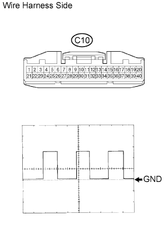
Disconnect the C10 meter connector.
Using an oscilloscope, check the signal waveform of the meter.
Tester Connection
| Tool Setting
| Vehicle Condition
|
C10-7 - Body ground
| 5 V/DIV., 10 msec./DIV.
| Engine idling
|
- OK:
- Refer to the illustration.
- HINT:
- As the engine speed increases, the wavelength shortens.
| | REPLACE COMBINATION METER ASSEMBLY |
|
|
| 2.CHECK WIRE HARNESS (METER - ECM) |
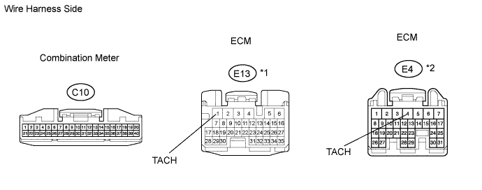
Disconnect the C10 meter connector.
Disconnect the E13*1 or E4*2 ECM connector.
- HINT:
- *1: 1GR-FE
- *2: 1KD-FTV
Measure the resistance of the wire harness side connectors.
- Standard resistance:
1GR-FETester Connection
| Specified Condition
|
C10-7 - E13-1 (TACH)
| Below 1 Ω
|
- 1KD-FTV:
Tester Connection
| Specified Condition
|
C10-7 - E4-4 (TACH)
| Below 1 Ω
|
| | REPAIR OR REPLACE HARNESS AND CONNECTOR |
|
|
| OK |
|
|
|
| GO TO SFI SYSTEM (1GR-FE), ECD SYSTEM (1KD-FTV) |
|