Meter / Gauge System -- Terminals Of Ecu |
| CHECK COMBINATION METER ASSEMBLY |
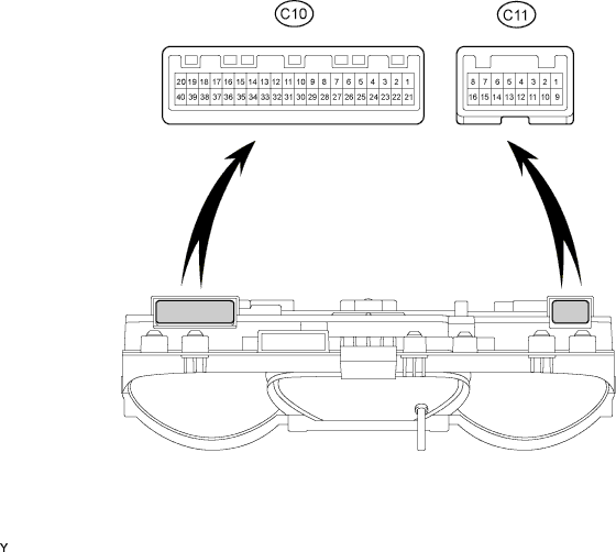
Disconnect the C10 and C11 meter connectors.
Measure the voltage and resistance of the wire harness side connectors.
Terminal No. Wiring Color Terminal Description Condition Specified Condition C10-1 - Body ground R - Body ground Battery Always 10 to 14 V C10-21 - C10-22 B-O - Y Ignition signal Ignition switch ON 10 to 14 V C10-21 - C10-22 B-O - Y Ignition signal Ignition switch OFF Below 1 V C11-11 - Body ground*1 B-R - Body ground Power supply for fuel consumption calculation Ignition switch ON 10 to 14 V C11-11 - Body ground*1 B-R - Body ground Power supply for fuel consumption calculation Ignition switch OFF Below 1 V C10-22 - Body ground Y - Body ground Ground Always Below 1 Ω C10-19 - Body ground*2 W-B - Body ground Ground Always Below 1 Ω C10-38 - Body ground*3 W-B - Body ground Ground Always Below 1 Ω C10-9 - Body ground*4 W-G - Body ground Rheostat signal Rheostat knob fully turned to left position 702 Ω C10-9 - Body ground*4 W-G - Body ground Rheostat signal Rheostat knob fully turned to right position Below 1 Ω C10-9 - Body ground*5 W-G - Body ground Rheostat signal Rheostat knob fully turned to right position Below 1 Ω - HINT:
- *1: for 1GR-FE
- *2: w/o Airbag
- *3: w/o ABS
- *4: w/ Light control rheostat
- *5: w/o Light control rheostat
Reconnect the C10 and C11 meter connectors.
Measure the voltage of the connectors.
Terminal No. Wiring Color Terminal Description Condition Specified Condition C10-2 - C10-3 BR - BR-Y Fuel level signal Ignition switch ON,
fuel level FBelow 1 V C10-2 - C10-3 BR - BR-Y Fuel level signal Ignition switch ON,
fuel level E4 to 7 V C10-5 - Body ground P-L - Body ground Vehicle speed signal (input) Ignition switch ON,
slowly turn wheelPulse generation
(see waveform 1)C10-6 - Body ground V-R - Body ground Vehicle speed signal (output) Vehicle is driven Pulse generation
(see waveform 1)C10-7 - Body ground B-W - Body ground Water temperature signal Engine running Pulse generation
(see waveform 2)C10-8 - C10-22 G - Y Light control switch signal Light control switch is OFF Below 1 V C10-8 - C10-22 G - Y Light control switch signal Light control switch is TAIL or HEAD 10 to 14 V C10-10 - Body ground G-Y - Body ground Unlock warning switch signal No key in ignition key cylinder Below 1 V C10-10 - Body ground G-Y - Body ground Unlock warning switch signal Ignition switch OFF,
key is in ignition key cylinder10 to 14 V C10-11 - Body ground R-Y - Body ground Driver side seat belt warning signal Ignition switch ON,
driver side seat belt unfastenedBelow 1 V C10-11 - Body ground R-Y - Body ground Driver side seat belt warning signal Ignition switch ON,
driver side seat belt fastened10 to 14 V C10-12 - C10-13*1 G-B - W-G Unengaged park warning signal Ignition switch ON,
A/T shift lever on P,
transfer shift lever not on P10 to 14 V C10-12 - C10-13*1 G-B - W-G Unengaged park warning signal Ignition switch ON,
A/T shift lever on P,
transfer shift lever on PBelow 1 V C10-14 - Body ground*2 W-G - Body ground Fuel filter warning signal Ignition switch ON,
fuel system warning light OFFBelow 1 V C10-14 - Body ground*2 W-G - Body ground Fuel filter warning signal Ignition switch ON,
fuel system warning light ON10 to 14 V C10-15 - Body ground R-B - Body ground Driver side door signal (output) Driver side door is closed Below 1 V C10-15 - Body ground R-B - Body ground Driver side door signal (output) Driver side door is open 10 to 14 V C10-16 - Body ground R-B - Body ground Driver side door signal (input) Driver side door is closed Below 1 V C10-16 - Body ground R-B - Body ground Driver side door signal (input) Driver side door is open 10 to 14 V C10-17 - Body ground R-L - Body ground Door signal All doors are closed Below 1 V C10-17 - Body ground R-L - Body ground Door signal All doors are open 10 to 14 V C10-18 - Body ground*6 P - Body ground ATF temperature warning signal Ignition switch ON,
ATF temperature warning light ONBelow 1 V C10-18 - Body ground*6 P - Body ground ATF temperature warning signal Ignition switch ON,
ATF temperature warning light OFF10 to 14 V C10-20 - Body ground*7 B-Y - Body ground SRS warning light signal Ignition switch ON,
SRS warning light OFFPulse generation
(see waveform 3)C10-20 - Body ground*7 B-Y - Body ground SRS warning light signal Ignition switch ON,
SRS warning light ONPulse generation
(see waveform 4)C10-23 - Body ground*2 L-R - Body ground Sedimenter warning signal Ignition switch ON,
fuel system warning light OFFBelow 1 V C10-23 - Body ground*2 L-R - Body ground Sedimenter warning signal Ignition switch ON,
fuel system warning light ON10 to 14 V C10-24 - C10-22 G-B - Y Turn signal indicator LH signal Ignition switch ON,
turn signal indicator LH light OFFBelow 1 V C10-24 - C10-22 G-B - Y Turn signal indicator LH signal Ignition switch ON,
turn signal indicator LH light ON10 to 14 V C10-25 - C10-22 G-Y - Y Turn signal indicator RH signal Ignition switch ON,
turn signal indicator RH light OFFBelow 1 V C10-25 - C10-22 G-Y - Y Turn signal indicator RH signal Ignition switch ON,
turn signal indicator RH light ON10 to 14 V C10-27 - Body ground R-Y - Body ground HI BEAM indicator signal HI BEAM indicator light OFF 10 to 14 V C10-27 - Body ground R-Y - Body ground HI BEAM indicator signal HI BEAM indicator light ON Below 1 V C10-28 - Body ground*3 L-B - Body ground Cruise indicator signal Ignition switch ON,
cruise control main switch OFF10 to 14 V C10-28 - Body ground*3 L-B - Body ground Cruise indicator signal Ignition switch ON,
cruise control main switch ONBelow 1 V C10-30 - Body ground*9 G-B - Body ground Front fog indicator signal Front fog light ON 10 to 14 V C10-30 - Body ground*9 G-B - Body ground Front fog indicator signal Front fog light OFF Below 1 V C10-31 - Body ground R-B - Body ground Center diff. lock indicator signal Ignition switch ON,
transfer shift lever on H4 or L410 to 14 V C10-31 - Body ground R-B - Body ground Center diff. lock indicator signal Ignition switch ON,
transfer shift lever in position other than H4 or L4Below 1 V C10-33 - Body ground B - Body ground Rear diff. lock indicator signal Ignition switch ON,
transfer indicator switch ONBelow 1 V C10-33 - Body ground B - Body ground Rear diff. lock indicator signal Ignition switch ON,
transfer indicator switch OFF10 to 14 V C10-35 - Body ground LG-B - Body ground Oil pressure warning signal Ignition switch ON,
oil pressure warning light OFF10 to 14 V C10-35 - Body ground LG-B - Body ground Oil pressure warning signal Ignition switch ON,
oil pressure warning light ONBelow 1 V C10-36 - Body ground LG - Body ground Brake warning signal Ignition switch ON,
brake warning light OFF10 to 14 V C10-36 - Body ground LG - Body ground Brake warning signal Ignition switch ON,
brake warning light ONBelow 1 V C10-37 - Body ground GR - Body ground Charge warning signal Ignition switch ON,
charge warning light OFF10 to 14 V C10-37 - Body ground GR - Body ground Charge warning signal Ignition switch ON,
charge warning light ONBelow 1 V C10-38 - Body ground*8 R-G - Body ground ABS warning indicator Ignition switch ON,
ABS warning light OFF10 to 14 V C10-38 - Body ground*8 R-G - Body ground ABS warning indicator Ignition switch ON,
ABS warning light ONBelow 1 V C10-39 - Body ground R-B - Body ground MIL signal Ignition switch ON,
MIL OFF10 to 14 V C10-39 - Body ground R-B - Body ground MIL signal Ignition switch ON,
MIL ONBelow 1 V C10-40 - Body ground*2 Y-R - Body ground Glow indicator signal Ignition switch ON,
glow indicator light OFF10 to 14 V C10-40 - Body ground*2 Y-R - Body ground Glow indicator signal Ignition switch ON,
glow indicator light ONBelow 1 V C11-1 - Body ground*4 GR-L - Body ground A/T shift position signal (L) Ignition switch ON,
A/T L indicator light OFFBelow 1 V C11-1 - Body ground*4 GR-L - Body ground A/T shift position signal (L) Ignition switch ON,
A/T L indicator light ON10 to 14 V C11-2 - Body ground*4 P-L - Body ground A/T shift position signal (2) Ignition switch ON,
A/T 2 indicator light OFFBelow 1 V C11-2 - Body ground*4 P-L - Body ground A/T shift position signal (2) Ignition switch ON,
A/T 2 indicator light ON10 to 14 V C11-3 - Body ground*4 L - Body ground A/T shift position signal (3) Ignition switch ON,
A/T 3 indicator light OFFBelow 1 V C11-3 - Body ground*4 L - Body ground A/T shift position signal (3) Ignition switch ON,
A/T 3 indicator light ON10 to 14 V C11-4 - Body ground*4 G-O - Body ground A/T shift position signal (4) Ignition switch ON,
A/T 4 indicator light OFFBelow 1 V C11-4 - Body ground*4 G-O - Body ground A/T shift position signal (4) Ignition switch ON,
A/T 4 indicator light ON10 to 14 V C11-5 - Body ground*4 B-R - Body ground A/T shift position signal (D) Ignition switch ON,
A/T D indicator light OFFBelow 1 V C11-5 - Body ground*4 B-R - Body ground A/T shift position signal (D) Ignition switch ON,
A/T D indicator light ON10 to 14 V C11-6 - Body ground*4 R-W - Body ground A/T shift position signal (N) Ignition switch ON,
A/T N indicator light OFFBelow 1 V C11-6 - Body ground*4 R-W - Body ground A/T shift position signal (N) Ignition switch ON,
A/T N indicator light ON10 to 14 V C11-9 - Body ground*2 G-B - Body ground Signal for amount of fuel consumption Engine running Pulse generation C11-10 - Body ground*5 L - Body ground Injector signal Engine running Pulse generation C11-14 - Body ground*4 R-Y - Body ground A/T shift position signal (R) Ignition switch ON,
A/T R indicator light OFFBelow 1 V C11-14 - Body ground*4 R-Y - Body ground A/T shift position signal (R) Ignition switch ON,
A/T R indicator light ON10 to 14 V - HINT:
- *1: for 4WD (A/T)
- *2: for 1KD-FTV, 5L-E
- *3: w/ Cruise control system
- *4: w/ A/T shift indicator light
- *5: for 1GR-FE
- *6: w/ A/T OIL TEMP indicator light
- *7: w/ Airbag
- *8: w/ ABS
- *9: w/ Front fog light
- If the result is not as specified, the combination meter may be malfunctioning.
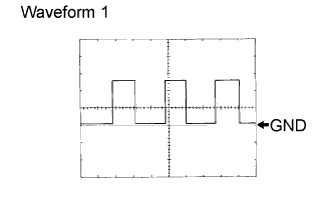
Using an oscilloscope, check the signal waveform of the meter.
Waveform 1 (Reference) Item Content Terminal No. C10-5 - Body ground
C10-6 - Body groundTool Setting 5 V/DIV., 10 msec./DIV. Vehicle Condition Driving at approx. 20 km/h (12 mph) - HINT:
- As vehicle speed increases, the wavelength shortens.
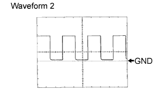
Using an oscilloscope, check the signal waveform of the meter.
Waveform 2 (Reference) Item Content Terminal No. C10-7 - Body ground Tool Setting 5 V/DIV., 10 msec./DIV. Vehicle Condition Engine idling - HINT:
- As vehicle speed increases, the wavelength shortens.
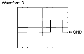
Using an oscilloscope, check the signal waveform of the meter.
Waveform 3 (Reference) Item Content Terminal No. C10-20 - Body ground Tool Setting 5 V/DIV., 50 msec./DIV. Vehicle Condition Ignition switch ON, SRS warning light OFF Using an oscilloscope, check the signal waveform of the meter.
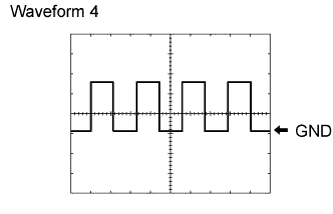
Waveform 4 (Reference) Item Content Terminal No. C10-20 - Body ground Tool Setting 5 V/DIV., 50 msec./DIV. Vehicle Condition Ignition switch ON, SRS warning light ON
 |
 |
 |
 |
| CHECK ACCESSORY METER ASSEMBLY (MULTI-DISPLAY) |

Disconnect the A23 meter connector.
Measure the voltage and resistance of the wire harness side connector.
If the result is not as specified, there may be a malfunction on the wire harness side.Symbols (Terminal No.) Wiring Color Terminal Description Condition Specified Condition +B (A23-14) - Body ground R - Body ground +B power supply Always 10 to 14 V IG (A23-12) - Body ground R-B - Body ground IG power supply Ignition switch ON 10 to 14 V IG (A23-12) - Body ground R-B - Body ground IG power supply Ignition switch OFF Below 1 V ACC (A23-13) - Body ground G-R - Body ground ACC power supply Ignition switch ACC 10 to 14 V ACC (A23-13) - Body ground G-R - Body ground ACC power supply Ignition switch OFF Below 1 V GND1 (A23-1) - Body ground LG - Body ground Ground Always Below 1 Ω SGND (A23-10) - Body ground BR - Body ground Ground Always Below 1 Ω Reconnect the A23 meter connector.
Measure the voltage of the connector.
If the result is not as specified, the accessory meter may be malfunctioning.Symbols (Terminal No.) Wiring Color Terminal Description Condition Specified Condition SG (A23-2) - TH+ (A23-3) BR-Y - W-G A/C ambient temperature sensor signal Ignition switch ON,
ambient temperature 25°C (77°F)1.35 to 1.75 V SG (A23-2) - TH+ (A23-3) BR-Y - W-G A/C ambient temperature sensor signal Ignition switch ON,
ambient temperature 40°C (104°F)0.85 to 2.34 V TAIL (A23-6) - Body ground G - Body ground Illumination signal Ignition switch ON,
light control switch OFFBelow 1 V TAIL (A23-6) - Body ground G - Body ground Illumination signal Ignition switch ON,
light control switch ON10 to 14 V
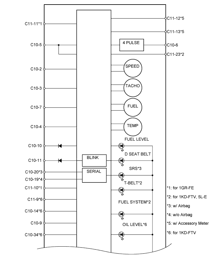

| Terminal No. | Wire Harness Side | |
| C10 | 1 | DOME Fuse |
| 2 | Fuel Suction with Pump and Gauge Tube | |
| 3 | Fuel Suction with Pump and Gauge Tube | |
| 4 | ECM | |
| 5 | Vehicle Speed Sensor | |
| 6 | 4 Pulse Output | |
| 7 | ECM | |
| 8 | Headlight Dimmer Switch | |
| 9 | Light Control Rheostat*1 Body ground*2 | |
| 10 | Unlock Warning Switch | |
| 11 | Front Seat Inner Belt (for Driver Side) | |
| 12 | Park / Neutral Position Switch*3 | |
| 13 | Transfer Neutral Detection Switch*4 | |
| 14 | Fuel Filter (Fuel Filter Switch)*5 | |
| 15 | Integration Relay | |
| 16 | Front Door Courtesy Light Switch (for Driver Side) | |
| 17 | Door Courtesy Light Switch | |
| 18 | ECM*6 | |
| 19 | Body ground*7 | |
| 20 | Center Airbag Sensor*8 | |
| 21 | MET Fuse | |
| 22 | Body Ground | |
| 23 | Fuel Filter (Fuel Sedimenter Switch)*5 | |
| 24 | Turn Signal Flasher Relay | |
| 25 | Turn Signal Flasher Relay | |
| 26 | - | |
| 27 | Headlight Dimmer Switch | |
| 28 | ECM*9 | |
| 29 | - | |
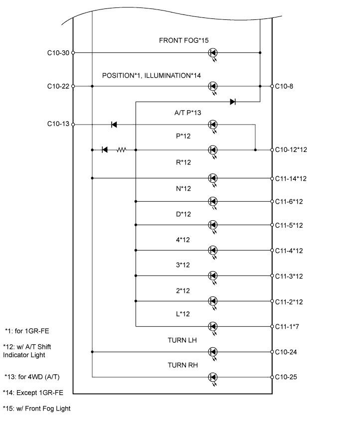
| 30 | Front Fog Light Switch*15 | |
| 31 | Transfer Indicator Switch*10 | |
| 32 | - | |
| 33 | 4WD Control ECU*11 | |
| 34 | Engine Oil Level Sensor*12 | |
| 35 | Oil Pressure Switch | |
| 36 | Parking Brake Switch Brake Fluid Level Warning Switch Vacuum Warning Switch*5 | |
| 37 | Generator Assembly | |
| 38 | Skid Control ECU with Actuator | |
| 39 | ECM (MIL) | |
| 40 | ECM (GLOW)*5 | |
| C11 | 1 | Shift Lock Control ECU*3 |
| 2 | Shift Lock Control ECU*3 | |
| 3 | Park / Neutral Position Switch*3 | |
| 4 | Shift Lock Control ECU*3 | |
| 5 | Shift Lock Control ECU*3 | |
| 6 | Park / Neutral Position Switch*3 | |
| 7 | - | |
| 8 | - | |
| 9 | ECM*12 | |
| 10 | Fuel Injector*13 | |
| 11 | INJ Fuse | |
| 12 | Accessory Meter (Multi-display)*14 | |
| 13 | Accessory Meter (Multi-display)*14 | |
| 14 | Park / Neutral Position Switch*3 | |
| 15 | - | |
| 16 | - | |
- HINT:
- *1: w/ Light control rheostat
- *2: w/o Light control rheostat
- *3: w/ A/T shift indicator light
- *4: for 4WD (A/T)
- *5: for 1KD-FTV, 5L-E
- *6: for 1GR-FE, 2TR-FE
- *7: w/o Airbag
- *8: w/ Airbag
- *9: w/ Cruise control system
- *10: w/ Center differential lock system
- *11: w/ Rear differential lock system
- *12 for 1KD-FTV
- *13: for 1GR-FE
- *14: w/ Accessory meter
- *15: w/ Front fog light