Dtc C1241/41 Low Battery Positive Voltage Or Abnormally High Battery Positive Voltage
DESCRIPTION
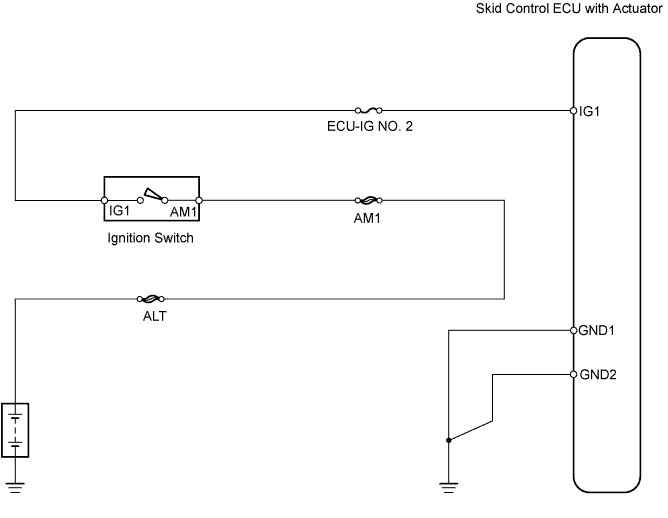
WIRING DIAGRAM
INSPECTION PROCEDURE
INSPECT FUSE (ECU-IG NO. 2)
INSPECT BATTERY
READ VALUE USING INTELLIGENT TESTER (ECU IG POWER VOLTAGE)
CHECK WIRE HARNESS (SKID CONTROL ECU - BATTERY)
CHECK WIRE HARNESS (SKID CONTROL ECU - BODY GROUND)
CHECK IF DTC OUTPUT RECURS
DTC C1241/41 Low Battery Positive Voltage or Abnormally High Battery Positive Voltage |
DESCRIPTION
This is the power source circuit of the skid control ECU.The skid control ECU has a built-in brake actuator.DTC No.
| DTC Detection Condition
| Trouble Area
|
C1241/41
| When either of following is detected:
1. Both conditions continue for at least 10 seconds
- Vehicle speed is more than 3 km/h (2 mph)
- IG1 terminal voltage is less than 9.5 V
2. All conditions continue for at least 0.2 seconds
- Solenoid relay remains ON
- Relay contact is open
- IG1 terminal voltage is less than 10 V
| - ECU-IG NO. 2 fuse
- Battery
- Charging system
- Power source circuit
|
WIRING DIAGRAM
INSPECTION PROCEDURE
| 1.INSPECT FUSE (ECU-IG NO. 2) |
Remove the ECU-IG NO. 2 fuse from the engine room junction block.
Measure the resistance of the fuse.
- Standard resistance:
- Below 1 Ω
Check the battery voltage.
- Standard voltage:
- 11 to 14 V
ResultResult
| Proceed to
|
Battery voltage is normal (when using intelligent tester)
| A
|
Battery voltage is normal (when not using intelligent tester)
| B
|
Battery voltage is abnormal
| C
|
| |
|
| | RECHARGE OR REPLACE BATTERY |
|
|
| 3.READ VALUE USING INTELLIGENT TESTER (ECU IG POWER VOLTAGE) |
Using the Data List, check for proper functioning of the ECU IG power voltage.
Skid control ECUTester Display
| Measurement Item/Range
| Normal Condition
| Diagnostic Note
|
ECU IG Power Voltage
| ECU power supply voltage / too Low, Normal or too High
| Normal
| -
|
ResultResult
| Proceed to
|
Display is Normal
| A
|
Display is not Normal
| B
|
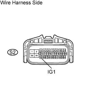
| 4.CHECK WIRE HARNESS (SKID CONTROL ECU - BATTERY) |
Disconnect the S2 ECU connector.
Turn the ignition switch ON.
Measure the voltage of the wire harness side connector.
- Standard voltage:
Tester Connection
| Specified Condition
|
S2-25 (IG1) - Body ground
| 10 to 14 V
|
| | REPAIR OR REPLACE HARNESS AND CONNECTOR |
|
|
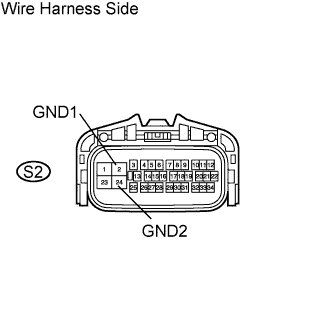
| 5.CHECK WIRE HARNESS (SKID CONTROL ECU - BODY GROUND) |
Disconnect the S2 ECU connector.
Measure the resistance of the wire harness side connector.
- Standard resistance:
Tester Connection
| Specified Condition
|
S2-2 (GND1) - Body ground
| Below 1 Ω
|
S2-24 (GND2) - Body ground
| Below 1 Ω
|
| | REPAIR OR REPLACE HARNESS AND CONNECTOR |
|
|
| 6.CHECK IF DTC OUTPUT RECURS |
Clear the DTCs.
Drive the vehicle at approximately 30 km/h (19 mph) or more for 60 seconds or more.
Check for DTCs.
ResultResult
| Proceed to
|
DTC is output
| A
|
DTC is not output
| B
|
| A |
|
|
|
| REPLACE BRAKE ACTUATOR ASSEMBLY |
|