Dtc C0278/11 Open In Abs Solenoid Relay Circuit
DESCRIPTION
WIRING DIAGRAM
INSPECTION PROCEDURE
INSPECT FUSE (ALT, ABS NO. 2)
CHECK WIRE HARNESS (SKID CONTROL ECU - BATTERY AND BODY GROUND)
RECONFIRM DTC
DTC C0278/11 Open in ABS Solenoid Relay Circuit |
DTC C0279/12 Short to B+ in ABS Solenoid Relay Circuit |
DESCRIPTION
This relay supplies power to each ABS solenoid. After the ignition switch is turned ON, if the ABS initial check completes, the skid control ECU turns the ABS solenoid relay on.DTC No.
| DTC Detection Condition
| Trouble Area
|
C0278/11
| When either of following is detected:
1. Both conditions continue for at least 0.2 seconds
- IG voltage is between 10 and 16 V
- Relay contact is open when relay is ON
2. Both conditions continue for at least 0.2 seconds
- IG voltage is less than 10 V
- Relay contact remains open when relay is ON
| - Brake actuator assembly (ABS solenoid relay)
- ABS solenoid relay circuit
|
C0279/12
| When relay is OFF, turning ignition switch ON closes relay contact immediately and continues for at least 0.2 seconds
| - Brake actuator assembly (ABS solenoid relay)
- ABS solenoid relay circuit
|
WIRING DIAGRAM
INSPECTION PROCEDURE
| 1.INSPECT FUSE (ALT, ABS NO. 2) |
Remove the ALT and ABS NO. 2 H-fuses from the engine room junction block.
Measure the resistance of the H-fuses.
- Standard resistance:
- Below 1 Ω
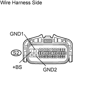
| 2.CHECK WIRE HARNESS (SKID CONTROL ECU - BATTERY AND BODY GROUND) |
Disconnect the S2 ECU connector.
Measure the voltage of the wire harness side connector.
- Standard voltage:
Tester Connection
| Specified Condition
|
S2-1 (+BS) - Body ground
| 10 to 14 V
|
Measure the resistance of the wire harness side connector.
- Standard resistance:
Tester Connection
| Specified Condition
|
S2-2 (GND1) - Body ground
| Below 1 Ω
|
S2-24 (GND2) - Body ground
| Below 1 Ω
|
| | REPAIR OR REPLACE HARNESS AND CONNECTOR |
|
|
These codes are output when a problem is detected in the brake actuator assembly.As the ABS motor relay is built into the brake actuator assembly, ABS motor relay and solenoid unit inspection cannot be performed.Be sure to check if the DTC is output before replacing the brake actuator assembly.Clear the DTCs.
Drive the vehicle at 6 km/h (4 mph) or more.
Check for DTCs.
ResultResult
| Proceed to
|
DTC is output
| A
|
DTC is not output
| B
|
| A |
|
|
|
| REPLACE BRAKE ACTUATOR ASSEMBLY |
|