Output Shaft -- Removal |
| 1. INSPECT 1ST GEAR THRUST CLEARANCE |
 |
Using a dial indicator, measure the thrust clearance.
- Standard clearance:
- 0.20 to 0.45 mm (0.0079 to 0.0177 in.)
| 2. INSPECT 2ND GEAR THRUST CLEARANCE |
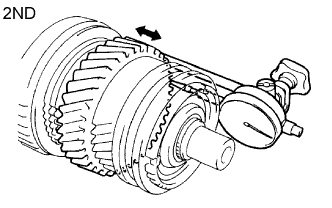 |
Using a dial indicator, measure the thrust clearance.
- Standard clearance:
- 0.10 to 0.25 mm (0.0039 to 0.0098 in.)
| 3. INSPECT 3RD GEAR THRUST CLEARANCE |
 |
Using a feeler gauge, measure the thrust clearance.
- Standard clearance:
- 0.10 to 0.25 mm (0.0039 to 0.0098 in.)
| 4. INSPECT 1ST GEAR RADIAL CLEARANCE |
 |
Using a dial indicator, measure the radial clearance.
- Standard clearance:
- 0.020 to 0.073 mm (0.0008 to 0.0029 in.)
| 5. INSPECT 2ND GEAR RADIAL CLEARANCE |
 |
Using a dial indicator, measure the radial clearance.
- Standard clearance:
- 0.015 to 0.068 mm (0.0006 to 0.0027 in.)
| 6. INSPECT 3RD GEAR RADIAL CLEARANCE |
 |
Using a dial indicator, measure the radial clearance.
- Standard clearance:
- 0.015 to 0.068 mm (0.0006 to 0.0027 in.)
| 7. REMOVE 1ST GEAR |
 |
Using SST and a press, press out the 5th gear, the output shaft center bearing, the 1st gear thrust washer and the 1st gear from the output shaft.
- SST
- 09950-00020
| 8. REMOVE NO. 1 SYNCHRONIZER RING SET (for 1st Gear) |
 |
Remove the synchronizer ring from the output shaft.
| 9. REMOVE 1ST GEAR THRUST WASHER PIN |
 |
Remove the thrust washer pin from the output shaft.
| 10. REMOVE 1ST GEAR NEEDLE ROLLER BEARING |
 |
Remove the needle roller bearing from the output shaft.
| 11. REMOVE 1ST GEAR BEARING SPACER |
 |
Remove the bearing spacer from the output shaft.
| 12. REMOVE BEARING SHAFT SNAP RING |
 |
Using 2 screwdrivers and a hammer, tap out the snap ring from the output shaft.
- NOTICE:
- Use a cloth to prevent the snap ring from flying off.
| 13. REMOVE 2ND GEAR |
 |
Using SST and a press, press out the No. 1 transmission clutch hub with the reverse gear, No. 1 synchronizer ring set and 2nd gear from the output shaft.
- SST
- 09950-00020
| 14. REMOVE 2ND GEAR NEEDLE ROLLER BEARING |
 |
Remove the needle roller bearing from the output shaft.
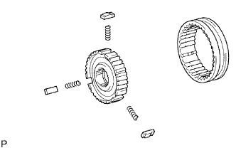
| 15. REMOVE REVERSE GEAR |
 |
Remove the reverse gear, 3 No. 1 synchromesh shifting keys, and 3 synchromesh shifting key springs.
- NOTICE:
- Use a cloth to prevent the shifting key and the shifting key springs from popping out.
| 16. REMOVE CLUTCH HUB SET SHAFT SNAP RING |
 |
Using a snap ring expander, remove the snap ring from the output shaft.
- NOTICE:
- Do not damage the sliding surface of the bearing.
| 17. REMOVE 3RD GEAR |
 |
Using SST and a press, press out the No. 2 transmission clutch hub (with the No. 2 transmission hub sleeve, No. 2 synchronizer ring and 3rd gear) from the output shaft.
- SST
- 09950-00020
| 18. REMOVE 3RD GEAR NEEDLE ROLLER BEARING |
 |
Remove the needle roller bearing from the output shaft.
| 19. REMOVE NO. 2 TRANSMISSION HUB SLEEVE |
 |
Remove the No. 2 hub sleeve, 3 No. 2 synchromesh shifting key springs, and 3 No. 2 synchromesh shifting keys from the No. 2 clutch hub.
| 20. INSPECT OUTPUT SHAFT |
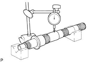 |
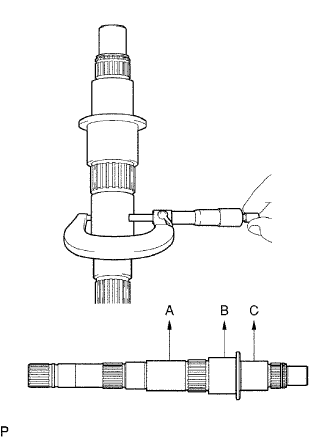
Using a dial indicator, measure the output shaft runout.
- Maximum runout:
- 0.03 mm (0.0012 in.)
Using a micrometer, measure the diameter at A, B and C on the output shaft.
- Standard diameter:
Mark Standard condition A 38.979 to 38.995 mm (1.5334 to 1.5352 in.) B 46.984 to 47.000 mm (1.8498 to 1.8504 in.) C 37.984 to 38.000 mm (1.4954 to 1.4961 in.)
 |
Using a micrometer, measure the thickness of the output shaft flange as shown in the illustration.
- Standard thickness:
- 4.8 to 5.2 mm (0.1890 to 0.2047 in.)
 |
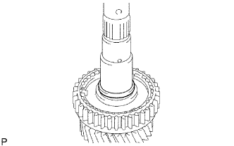
| 21. INSPECT 3RD GEAR |
 |
Using a cylinder gauge, measure the inside diameter of the 3rd gear.
- Standard inside diameter:
- 44.015 to 44.040 mm (1.7329 to 1.7339 in.)
- Maximum inside diameter:
- 44.040 mm (1.7339 in.)
| 22. INSPECT 2ND GEAR |
 |
Using a cylinder gauge, measure the inside diameter of the 2nd gear.
- Standard inside diameter:
- 53.015 to 53.040 mm (2.0872 to 2.0881 in.)
- Maximum inside diameter:
- 53.040 mm (2.0881 in.)
| 23. INSPECT 1ST GEAR |
 |
Using a cylinder gauge, measure the inside diameter of the 1st gear.
- Standard inside diameter:
- 46.015 to 46.040 mm (1.812 to 1.8126 in.)
- Maximum inside diameter:
- 46.040 mm (1.8126 in.)
| 24. INSPECT 1ST GEAR THRUST WASHER |
 |
Using a micrometer, measure the thickness of the thrust washer.
- Standard thickness:
- 5.95 to 6.05 mm (0.2346 to 0.2382 in.)
- Minimum thickness:
- 5.95 mm (0.2346 in.)
| 25. INSPECT NO. 1 SYNCHRONIZER RING SET (for 1st Gear) |
 |
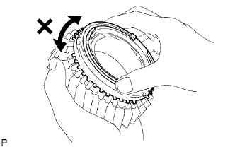
Apply gear oil to the cone of the 1st gear, and check that it does not turn in both directions while pushing the No. 1 synchronizer ring set.
If it turns, replace the synchronizer ring.
Measure the clearance between the No. 1 synchronizer ring and 1st gear while pushing the No. 1 synchronizer ring to the cone of the 1st gear.
- Standard clearance:
- 0.65 to 1.75 mm (0.0256 to 0.0689 in.)
 |
| 26. INSPECT NO. 1 SYNCHRONIZER RING SET (for 2nd Gear) |
Apply gear oil to the cone of the 2nd gear, and check that it does not turn in both directions while pushing the No. 1 synchronizer ring set.
If it turns, replace the No. 1 synchronizer ring set.
 |
Push the No. 1 synchronizer ring set to the cone of the 2nd gear. Measure the clearance between the No. 1 synchronizer ring set and 2nd gear.
- Standard clearance:
- 0.65 to 1.75 mm (0.0256 to 0.0689 in.)
 |
| 27. INSPECT NO. 2 SYNCHRONIZER RING (for 3rd Gear) |
 |
Apply gear oil to the cone of the 3rd gear, and check that it does not turn in both directions while pushing the No. 2 synchronizer ring.
If it turns, replace the No. 2 synchronizer ring.
Push the No. 2 synchronizer ring to the cone of the 3rd gear. Measure the clearance between the No. 2 synchronizer ring and 3rd gear.
- Standard clearance:
- 0.75 to 1.65 mm (0.0295 to 0.0650 in.)
 |
| 28. INSPECT REVERSE GEAR |
 |
Using a vernier caliper, measure the groove of the reverse gear and the thickness of the claw of the No. 1 shift fork. Then check the clearance between the groove and claw.
- Standard clearance:
- 0.15 to 0.41 mm (0.0060 to 0.0161 in.)
| 29. INSPECT NO. 1 TRANSMISSION CLUTCH HUB |
 |
Check the sliding condition between the No. 1 clutch hub and the reverse gear.
Check the tip of the spline gear sleeve of the reverse gear for wear.
If there are any defects, replace the No. 1 clutch hub.
| 30. INSPECT NO. 2 TRANSMISSION HUB SLEEVE |
 |
Using a vernier caliper, measure the No. 2 hub sleeve groove and the thickness of the claw of the No. 2 shift fork.
- Standard clearance:
- 0.15 to 0.35 mm (0.0059 to 0.0138 in.)
| 31. INSPECT NO. 2 TRANSMISSION CLUTCH HUB |
 |
Check the sliding condition between the No. 2 clutch hub and No. 2 hub sleeve.
Check the tip of the spline gear of the No. 1 clutch hub for wear.
Check the tip of the spline gear sleeve of the reverse gear for wear.
If there are any defects, replace the No. 1 clutch hub or reverse gear.