Automatic Transmission Assembly -- Installation |
| 1. INSPECT TORQUE CONVERTER ASSEMBLY |
| 2. INSTALL TORQUE CONVERTER ASSEMBLY |
 |
Install the torque converter clutch to the automatic transmission.
Using a vernier caliper and straightedge, measure dimension A between the transmission and the end surface of the drive plate.
- Standard:
- A = 22.28 mm (0.8772 in.)
Using a vernier caliper and straightedge, measure dimension B shown in the illustration. Check that B is greater than A.
- Standard:
- B = A + 1.00 mm (0.0394 in.) or more
 |
| 3. INSTALL TRANSFER ASSEMBLY |
| 4. INSTALL NO. 1 ENGINE MOUNTING INSULATOR REAR |
 |
Install the engine mounting insulator to the transmission with the 4 bolts.
- Torque:
- 47 N*m{479 kgf*cm, 35 ft.*lbf}
| 5. INSTALL AUTOMATIC TRANSMISSION ASSEMBLY |
 |
Install the transmission to the engine with the 5 bolts.
- Torque:
- 71 N*m{720 kgf*cm, 53 ft.*lbf}
- NOTICE:
- Do not twist or apply excessive force to the automatic transaxle assembly.
- Check that the torque converter rotates smoothly after installation of the automatic transaxle assembly.
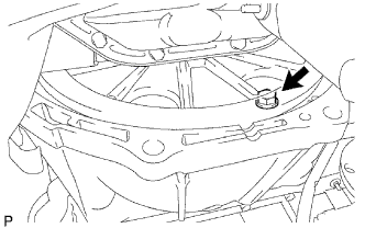
| 6. INSTALL DRIVE PLATE AND TORQUE CONVERTER SETTING BOLT |
Hold the crankshaft pulley bolt with a wrench and install the 6 drive plate and torque converter setting bolts.
- Torque:
- 48 N*m{489 kgf*cm, 35 ft.*lbf}
- NOTICE:
- First install the black colored bolt and then the remaining 5 silver colored bolts.
 |
| 7. INSTALL STIFFENER PLATE |
 |
Install the No. 2 end plate.
Install the No. 4 cylinder block insulator.
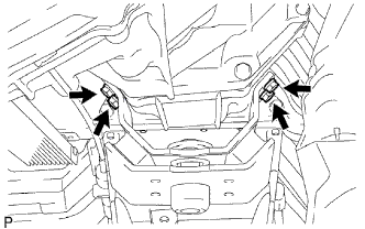
Install the stiffener plate LH to the engine and transmission with the 4 bolts.
- Torque:
- 71 N*m{720 kgf*cm, 53 ft.*lbf}
Install the stiffener plate RH (with clamp tube) to the engine and transmission with the 4 bolts.
- Torque:
- 71 N*m{720 kgf*cm, 53 ft.*lbf}
| 8. CONNECT WIRE HARNESS |
| 9. CONNECT CONNECTOR |
Transmission side:
Connect the connectors.Connect the temperature sensor connector.
Connect the park/neutral position switch connector.
Connect the 2 speed sensor connectors.
Connect the transmission wire connector.
Transfer side:
Connect the connectors.Connect the indicator switch connector (4WD).
Connect the speedometer sensor connector.
Connect the indicator switch connector (L4).
Connect the indicator switch connector (neutral).
| 10. INSTALL NO. 3 FRAME CROSSMEMBER SUB-ASSEMBLY |
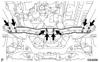 |
Install the frame crossmember with the 4 bolts and 4 nuts.
- Torque:
- 50 N*m{510 kgf*cm, 37 ft.*lbf}
Install the 4 set bolts of the engine mounting insulator.
- Torque:
- 27 N*m{275 kgf*cm, 20 ft.*lbf}
| 11. INSTALL STARTER ASSEMBLY |
Install the starter and ground cable with the 2 nuts and bolt.
- Torque:
- 68 N*m{693 kgf*cm, 50 ft.*lbf}
 |
Install the starter wire to terminal 30 with the nut.
- Torque:
- 9.8 N*m{100 kgf*cm, 87 in.*lbf}
Connect the starter connector.
Attach the terminal cap.
| 12. INSTALL TRANSMISSION CONTROL CABLE BRACKET |
 |
Install the control cable bracket with the 2 bolts.
- Torque:
- 28 N*m{286 kgf*cm, 21 ft.*lbf}
| 13. CONNECT TRANSMISSION CONTROL SHIFT CABLE ASSEMBLY |
 |
Connect the control cable with the clip.
Connect the control cable with the nut.
- Torque:
- 14 N*m{143 kgf*cm, 10 ft.*lbf}
| 14. INSTALL OIL COOLER TUBE |
 |
Loosely install the tip of the oil cooler tube inlet to the automatic transmission by hand.
Loosely install the tip of the oil cooler tube outlet to the automatic transmission by hand.
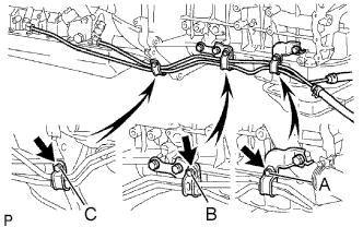
Install the 3 clamps with the 3 bolts.
- Torque:
- 5.0 N*m{51 kgf*cm, 44 in.*lbf} for A and B
- 12 N*m{122 kgf*cm, 9 ft.*lbf} for C
Using a 17mm union nut wrench, tighten the inlet and outlet tubes.
- Torque:
- 34 N*m{350 kgf*cm, 25 ft.*lbf}
- NOTICE:
- Use the formula to calculate special torque values for situations where a union nut wrench is combined with a torque wrench (Toyota Fortuner RM000000UYX010X.html).
 |
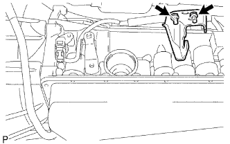
| 15. INSTALL TRANSMISSION OIL FILLER TUBE SUB-ASSEMBLY |
 |
Coat a new O-ring with ATF, and install it to the oil filler tube.
Install the oil filler tube to the transmission with the 2 bolts.
- Torque:
- 12 N*m{122 kgf*cm, 9 ft.*lbf}
Install the oil level gauge.
| 16. INSTALL PROPELLER SHAFT WITH CENTER BEARING ASSEMBLY |
| 17. INSTALL FRONT PROPELLER SHAFT ASSEMBLY |
| 18. INSTALL FRONT EXHAUST PIPE ASSEMBLY |
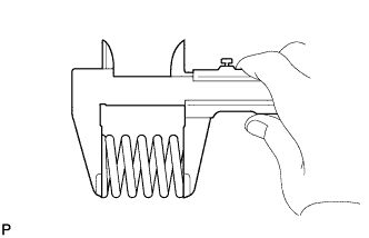
Using a vernier caliper, measure the free length of the compression spring.
- Minimum length:
- 40 mm (1.57 in.)
 |
Install the front pipe to the pipe support.
Install a new gasket to the outlet pipe.
- NOTICE:
- Be careful with the installation direction of the gasket.
- Do not reuse the gasket.
- To ensure a proper seal, do not use the front pipe to force the gasket onto the outlet pipe.
- HINT:
- Using a plastic-faced hammer, uniformly strike the gasket so that the gasket and outlet pipe are properly fit.
 |
Install the front pipe with the 2 compression springs and 2 bolts. Alternately tighten the bolts in several passes.
- Torque:
- 43 N*m{438 kgf*cm, 32 ft.*lbf}
| 19. INSTALL TRANSFER HIGH AND LOW SHIFT LEVER ASSEMBLY |
 |
Install the transfer shift lever to the shift lever retainer.
- HINT:
- Apply MP grease to the tip of the transfer shift lever.
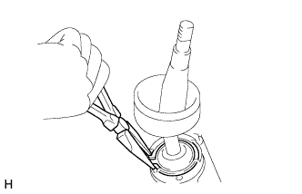
Using needle-nose pliers, install the snap ring.
| 20. INSTALL SHIFT LEVER BOOT ASSEMBLY |
Install the shift lever boot with the 4 screws.
| 21. ADD AUTOMATIC TRANSMISSION FLUID |
| 22. CONNECT CABLE TO NEGATIVE BATTERY TERMINAL |
- NOTICE:
- When disconnecting the cable, some systems need to be initialized after the cable is reconnected (Toyota Fortuner RM000002HD2006X.html).
| 23. INSPECT AND ADJUST SHIFT LEVER POSITION |
| 24. INSTALL CONSOLE BOX ASSEMBLY |
| 25. CHECK FOR EXHAUST GAS LEAKS |
| 26. INSPECT AUTOMATIC TRANSMISSION FLUID LEVEL |
| 27. INSTALL NO. 2 ENGINE UNDER COVER |
Install the under cover with the 4 bolts.
- Torque:
- 28 N*m{286 kgf*cm, 21 ft.*lbf}
| 28. INSTALL NO. 1 ENGINE UNDER COVER |
Install the under cover with the 8 bolts.
- Torque:
- 28 N*m{286 kgf*cm, 21 ft.*lbf}