Rear Differential Carrier Assembly Reassembly
ASSEMBLE DIFFERENTIAL CASE
INSTALL DIFFERENTIAL RING GEAR
INSTALL REAR DIFFERENTIAL CASE BEARING
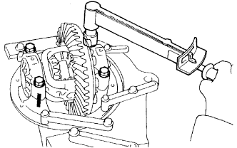
INSPECT DIFFERENTIAL RING GEAR RUNOUT
INSTALL REAR DIFFERENTIAL DUST DEFLECTOR
INSTALL REAR DRIVE PINION FRONT TAPERED ROLLER BEARING
INSTALL REAR DRIVE PINION REAR TAPERED ROLLER BEARING
INSTALL REAR DRIVE PINION REAR TAPERED ROLLER BEARING
ADJUST DIFFERENTIAL DRIVE PINION PRELOAD
INSTALL DIFFERENTIAL CASE ASSEMBLY
INSTALL REAR DIFFERENTIAL BEARING ADJUSTING NUT
INSPECT AND ADJUST BACKLASH OF DIFFERENTIAL RING GEAR AND DIFFERENTIAL DRIVE PINION
INSPECT TOTAL PRELOAD
INSPECT TOOTH CONTACT BETWEEN RING GEAR AND DRIVE PINION
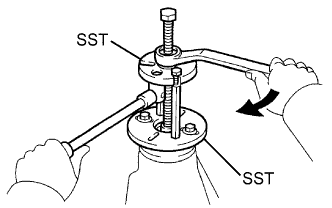
REMOVE REAR DRIVE PINION NUT
REMOVE REAR DRIVE PINION COMPANION FLANGE SUB-ASSEMBLY
REMOVE REAR DIFFERENTIAL DRIVE PINION OIL SLINGER
REMOVE REAR DRIVE PINION FRONT TAPERED ROLLER BEARING
INSTALL REAR DIFFERENTIAL DRIVE PINION BEARING SPACER
INSTALL DIFFERENTIAL OIL STORAGE RING
INSTALL REAR DRIVE PINION FRONT TAPERED ROLLER BEARING
INSTALL REAR DIFFERENTIAL DRIVE PINION OIL SLINGER
INSTALL REAR DIFFERENTIAL CARRIER OIL SEAL
INSTALL REAR DRIVE PINION COMPANION FLANGE SUB-ASSEMBLY
INSPECT DRIVE PINION PRELOAD
INSPECT TOTAL PRELOAD
INSPECT DIFFERENTIAL RING GEAR BACKLASH
INSPECT RUNOUT OF REAR DRIVE PINION COMPANION FLANGE SUB-ASSEMBLY
STAKE DRIVE PINION NUT
INSTALL REAR DIFFERENTIAL BEARING ADJUSTING NUT LOCK
Rear Differential Carrier Assembly -- Reassembly |
| 1. ASSEMBLE DIFFERENTIAL CASE |
Install the side gear thrust washer to the side gear.
- HINT:
- Using the table below, select 2 thrust washers which will ensure that the backlash is within the specifications.
- Standard washer thickness:
Thickness
| Thickness
|
1.48 to 1.52 mm (0.058 to 0.060 in.)
| 1.73 to 1.77 mm (0.068 to 0.070 in.)
|
1.53 to 1.57 mm (0.060 to 0.062 in.)
| 1.78 to 1.82 mm (0.070 to 0.072 in.)
|
1.58 to 1.62 mm (0.062 to 0.064 in.)
| 1.83 to 1.87 mm (0.072 to 0.074 in.)
|
1.63 to 1.67 mm (0.064 to 0.066 in.)
| 1.88 to 1. 92 mm (0.074 to 0.076 in.)
|
1.68 to 1.72 mm (0.066 to 0.068 in.)
| -
|
Install the 2 side gears (with thrust washers), 2 pinion gears, 2 pinion thrust washers and pinion shaft in the differential case.
- HINT:
- Align the holes of the differential case and pinion shaft.
Measure the side gear backlash.
Using a dial indicator, measure the side gear backlash while holding one pinion gear toward the differential case.
- Standard backlash:
- 0.05 to 0.20 mm (0.002 to 0.008 in.)
- If the backlash is not as specified, install 2 side gear thrust washers with different thicknesses.
Using a pin punch and hammer, tap in the straight pin through the differential case and hole of the pinion shaft.
Stake the differential case.
| 2. INSTALL DIFFERENTIAL RING GEAR |
Clean the contact surfaces of the differential case and ring gear.
Heat the ring gear in boiling water that is approximately 100°C (212°F).
Carefully remove the ring gear from the boiling water.
After the moisture on the ring gear has completely evaporated, quickly install the ring gear to the differential case.
Align the matchmarks on the ring gear with those of the differential case.
Temporarily install 5 new lock plates and 10 bolts.
After the ring gear cools down, install the 10 bolts by diametrically tightening the bolts uniformly in several passes.
- Torque:
- 84 N*m{857 kgf*cm, 62 ft.*lbf}
Using a chisel and hammer, stake the 5 lock plates.
- HINT:
- Strike the tab labeled A so that it is flush with the flat surface of the bolt. Strike the tab labeled B so that half of the tab contacts the bolt as shown in the illustration.
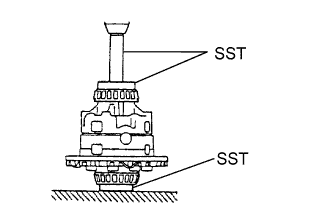
| 3. INSTALL REAR DIFFERENTIAL CASE BEARING |
Using SST and a press, press the bearing onto the differential case.
- SST
- 09950-60010(09951-00430,09951-00480,09951-00470,09951-00550)
09950-70010(09951-07150,09951-00560,09951-00570)
| 4. INSPECT DIFFERENTIAL RING GEAR RUNOUT |
Install the differential case on the carrier, and install the 2 adjusting nuts so that there is no play in the bearing.
Install the 2 bearing caps with the 4 bolts.
- Torque:
- 85 N*m{870 kgf*cm, 63 ft.*lbf}
Using a dial indicator, measure the runout of the ring gear.
- Maximum runout:
- 0.07 mm (0.0028 in.)
Remove the 2 bearing caps, 2 adjusting nuts and differential case.
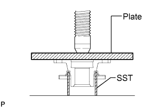
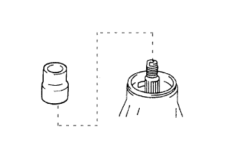
| 5. INSTALL REAR DIFFERENTIAL DUST DEFLECTOR |
Using SST, a plate and a press, press in a new dust deflector.
- SST
- 09636-20010
- NOTICE:
- Be careful not to damage the dust deflector.
| 6. INSTALL REAR DRIVE PINION FRONT TAPERED ROLLER BEARING |
Using SST and a press, press the roller bearing (outer) to the carrier.
- SST
- 09316-60011(09316-00011,09316-00021)
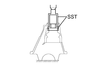
| 7. INSTALL REAR DRIVE PINION REAR TAPERED ROLLER BEARING |
Using SST and a press, press the roller bearing (outer) into the carrier.
- SST
- 09316-60011(09316-00041,09316-00011)
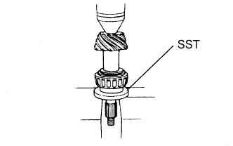
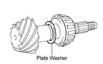
| 8. INSTALL REAR DRIVE PINION REAR TAPERED ROLLER BEARING |
Install the plate washer on the drive pinion.
- HINT:
- First fit a washer with the same thickness as the removed washer, and then check the tooth contact pattern. Replace the washer with one of a different thickness if necessary.
Using SST and a press, press the roller bearing (inner) onto the drive pinion.
- SST
- 09506-30012
| 9. ADJUST DIFFERENTIAL DRIVE PINION PRELOAD |
Install the drive pinion, rear drive pinion front tapered roller bearing and rear differential drive pinion oil slinger.
- HINT:
- Assemble the spacer and oil seal after adjusting the gear contact pattern.
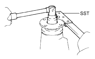
Using SST, install the companion flange.
- SST
- 09950-30012(09951-03010,09953-03010,09954-03010,09955-03030,09956-03040)
- NOTICE:
- Before using SST (center bolt), apply hypoid gear oil to its threads and tip.
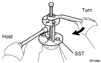
Adjust the drive pinion preload by tightening the companion flange nut.
Using SST to hold the companion flange in place, torque the nut.
- SST
- 09330-00021(09330-00030)
- Torque:
- 370 N*m{3770 kgf*cm, 273 ft.*lbf}
- NOTICE:
- As there is no spacer, torque a little at a time. Be careful not to overtighten the nut.
- Apply hypoid gear oil LSD to the nut.
Using a torque wrench, measure the preload.
- Standard preload (at start of torque):
Bearing
| Specified Condition
|
New bearing
| 1.05 to 1.64 N*m (10.7 to 16.7 kgf*cm, 9.3 to 14.5 in.*lbf)
|
Reused bearing
| 0.56 to 0.85 N*m (5.7 to 8.7 kgf*cm, 4.9 to 7.5 in.*lbf)
|
- NOTICE:
- For a more accurate measurement, rotate the bearing forward and backward several times before measuring.
| 10. INSTALL DIFFERENTIAL CASE ASSEMBLY |
Place the 2 bearing outer races on their respective bearings.
- HINT:
- Make sure the right and left races are not interchanged.
| 11. INSTALL REAR DIFFERENTIAL BEARING ADJUSTING NUT |
Install the 2 adjusting nuts on the carrier, making sure that the nuts are threaded properly.
| 12. INSPECT AND ADJUST BACKLASH OF DIFFERENTIAL RING GEAR AND DIFFERENTIAL DRIVE PINION |
Align the matchmarks on the caps and carrier.
Install the right and left bearing caps with the 4 bolts.
- Torque:
- 85 N*m{870 kgf*cm, 63 ft.*lbf}
- If the bearing cap does not fit tightly on the carrier, the adjusting nuts are not threaded properly.
- HINT:
- Reinstall the adjusting nuts if necessary.
Loosen the 4 bearing cap bolts to the point where the adjusting nuts can be turned by SST.
Using SST, torque the adjusting nut on the ring gear side until the ring has a backlash of about 0.2 mm (0.008 in.).
- SST
- 09504-00011
09960-10010(09962-01000,09963-00700)
While turning the ring gear, use SST to fully tighten the adjusting nut on the drive pinion side. After the bearings have settled, loosen the adjusting nut on the drive pinion side.
Using SST, tighten the adjusting nut 1 to 1.5 notches from the 0 preload position.
Using a dial indicator, adjust the ring gear backlash until it is within the specification.
- Standard backlash:
- 0.13 to 0.18 mm (0.0051 to 0.0071 in.)
- HINT:
- The backlash is adjusted by turning the left and right adjusting nuts by an equal amount. For example, loosen the nut on the right side one notch and loosen the nut on the left side one notch.
- Perform the measurements at 3 or more positions around the circumference of the ring gear.
Torque the bearing cap bolts.
- Torque:
- 85 N*m{870 kgf*cm, 63 ft.*lbf}
| 13. INSPECT TOTAL PRELOAD |
Using a torque wrench, measure the preload with the teeth of the drive pinion and ring gear in contact.
- Standard total preload (at start of torque):
- 0.39 to 0.59 N*m (4 to 6 kgf*cm, 3.4 to 5.2 in.*lbf) + drive pinion preload
- If necessary, disassemble and inspect the differential.
| 14. INSPECT TOOTH CONTACT BETWEEN RING GEAR AND DRIVE PINION |
Coat 3 or 4 teeth at 3 different positions on the ring gear with red lead primer.
Hold the companion flange firmly in place and rotate the ring gear in both directions.
Inspect the tooth contact pattern.
- If the teeth are not contacting properly, use the following chart to select a proper washer.
- Standard plate washer thickness:
Thickness
| Thickness
|
1.69 to 1.71 mm (0.0665 to 0.0673 in.)
| 2.02 to 2.04 mm (0.0795 to 0.0803 in.)
|
1.72 to 1.74 mm (0.0677 to 0.0685 in.)
| 2.05 to 2.07 mm (0.0807 to 0.0815 in.)
|
1.75 to 1.77 mm (0.0689 to 0.0697 in.)
| 2.08 to 2.10 mm (0.0819 to 0.0827 in.)
|
1.78 to 1.80 mm (0.0701 to 0.0709 in.)
| 2.11 to 2.13 mm (0.0831 to 0.0839 in.)
|
1.81 to 1.83 mm (0.0713 to 0.0720 in.)
| 2.14 to 2.16 mm (0.0843 to 0.0850 in.)
|
1.84 to 1.86 mm (0.0724 to 0.0732 in.)
| 2.17 to 2.19 mm (0.0854 to 0.0862 in.)
|
1.87 to 1.89 mm (0.0736 to 0.0744 in.)
| 2.20 to 2.22 mm (0.0866 to 0.0874 in.)
|
1.90 to 1.92 mm (0.0748 to 0.0756 in.)
| 2.23 to 2.25 mm (0.0878 to 0.0886 in.)
|
1.93 to 1.95 mm (0.0760 to 0.0768 in.)
| 2.26 to 2.28 mm (0.0890 to 0.0898 in.)
|
1.96 to 1.98 mm (0.0772 to 0.0780 in.)
| 2.29 to 2.31 mm (0.0902 to 0.0909 in.)
|
1.99 to 2.01 mm (0.0783 to 0.0791 in.)
| 2.32 to 2.34 mm (0.0913 to 0.0921 in.)
|
| 15. REMOVE REAR DRIVE PINION NUT |
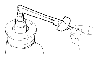
Using SST and a hammer, loosen the staked part of the nut.
- SST
- 09930-00010(09931-00010,09931-00020)
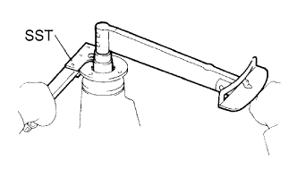
Using SST to hold the companion flange in place, remove the nut.
- SST
- 09330-00021(09330-00030)
| 16. REMOVE REAR DRIVE PINION COMPANION FLANGE SUB-ASSEMBLY |
| 17. REMOVE REAR DIFFERENTIAL DRIVE PINION OIL SLINGER |
| 18. REMOVE REAR DRIVE PINION FRONT TAPERED ROLLER BEARING |
Using SST, remove the roller bearing (outer) from the carrier.
- SST
- 09308-00010
Using a brass bar and hammer, tap out the oil storage ring from the carrier.
- HINT:
- If the bearing is damaged during removal, replace it.
| 19. INSTALL REAR DIFFERENTIAL DRIVE PINION BEARING SPACER |
Install a new bearing spacer to the drive pinion.
| 20. INSTALL DIFFERENTIAL OIL STORAGE RING |
Using a brass bar and hammer, tap in a new oil storage ring.
- NOTICE:
- Be careful not to damage the oil storage ring.
| 21. INSTALL REAR DRIVE PINION FRONT TAPERED ROLLER BEARING |
| 22. INSTALL REAR DIFFERENTIAL DRIVE PINION OIL SLINGER |
| 23. INSTALL REAR DIFFERENTIAL CARRIER OIL SEAL |
for TMC Made:
Using SST and a hammer, tap in a new oil seal.
- SST
- 09554-30011
- Standard oil seal depth:
- 0 +/-0.3 mm (0 +/-0.0118 in.)
Apply MP grease to the lip of the oil seal.
for DANA Made:
Using a brass bar and hammer, tap in a new oil seal until its surface is flush with the differential carrier end.
- NOTICE:
- Do not damage the oil seal.
Apply MP grease to the lip of the oil seal.
| 24. INSTALL REAR DRIVE PINION COMPANION FLANGE SUB-ASSEMBLY |
Using SST, install the companion flange on the drive pinion.
- SST
- 09950-30012(09951-03010,09953-03010,09954-03010,09955-03030,09956-03040)
- NOTICE:
- Before using SST (center bolt), apply hypoid gear oil to its threads and tip.
Coat the threads of a new nut with hypoid gear oil LSD.
Using SST to hold the flange, torque the nut.
- SST
- 09330-00021(09330-00030)
- Torque:
- 370 N*m{3770 kgf*cm, 273 ft.*lbf}or less
| 25. INSPECT DRIVE PINION PRELOAD |
Using a torque wrench, measure the preload of the backlash between the drive pinion and ring gear.
- Standard preload (at start of torque):
Bearing
| Specified Condition
|
New bearing
| 1.05 to 1.64 N*m (11 to 17 kgf*cm, 9.3 to 15 in.*lbf)
|
Reused bearing
| 0.56 to 0.85 N*m (6 to 9 kgf*cm, 4.9 to 7.5 in.*lbf)
|
- If the preload is greater than the maximum, replace the bearing spacer.
- If the preload is less than the minimum, retighten the nut with 13 N*m (130 kgf*cm, 9 ft.*lbf) of torque at a time until the specified preload is reached.
- Torque:
- 370 N*m{3770 kgf*cm, 273 ft.*lbf}or less
- If the maximum torque is exceeded while retightening the nut, replace the bearing spacer and repeat the preload adjusting procedure.
- HINT:
- Do not loosen the pinion nut to reduce the preload.
| 26. INSPECT TOTAL PRELOAD |
Using a torque wrench, measure the preload.
- Standard total preload:
- 0.22 to 0.85 N*m (2 to 9 kgf*cm, 1.9 to 7.7 in.*lbf) + drive pinion preload
- If necessary, disassemble and inspect the differential.
| 27. INSPECT DIFFERENTIAL RING GEAR BACKLASH |
Using a dial indicator, check the backlash of the ring gear.
- Standard backlash:
- 0.13 to 0.18 mm (0.0051 to 0.0071 in.)
- If the backlash is not as specified, adjust the side bearing preload or repair as necessary.
- HINT:
- Perform the measurements at 3 or more positions around the circumference of the ring gear.
| 28. INSPECT RUNOUT OF REAR DRIVE PINION COMPANION FLANGE SUB-ASSEMBLY |
Using a dial indicator, measure the runout of the drive pinion companion flange vertically and laterally.
- Maximum runout:
Runout
| Specified Condition
|
Vertical runout
| 0.10 mm (0.0039 in.)
|
Lateral runout
| 0.10 mm (0.0039 in.)
|
- If the runout is greater than the maximum, replace the companion flange.
| 29. STAKE DRIVE PINION NUT |
Using a chisel and hammer, stake the nut.
| 30. INSTALL REAR DIFFERENTIAL BEARING ADJUSTING NUT LOCK |
Install 2 new adjusting nut locks on the bearing caps with the 2 bolts.
- Torque:
- 13 N*m{130 kgf*cm, 9 ft.*lbf}
Bend the nut locks.
- HINT:
- Perform the measurements at 3 or more positions around the circumference of the ring gear.