Anti-Lock Brake System Tc And Cg Terminal Circuit
DESCRIPTION
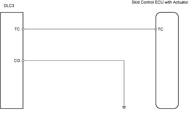
WIRING DIAGRAM
INSPECTION PROCEDURE
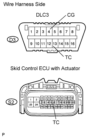
CHECK WIRE HARNESS (DLC3 - SKID CONTROL ECU AND BODY GROUND)
ANTI-LOCK BRAKE SYSTEM - TC and CG Terminal Circuit |
DESCRIPTION
Connecting terminals TC and CG of the DLC3 causes the ECU to display DTCs through ABS warning light blinking patterns.
WIRING DIAGRAM
INSPECTION PROCEDURE
| 1.CHECK WIRE HARNESS (DLC3 - SKID CONTROL ECU AND BODY GROUND) |
Disconnect the S2 ECU connector.
Measure the resistance of the wire harness side connectors.
- Standard resistance:
Tester Connection
| Specified Condition
|
D3-4 (CG) - Body ground
| Below 1 Ω
|
D3-13 (TC) - S2-16 (TC)
| Below 1 Ω
|
S2-16 (TC) - Body ground
| 10 kΩ or higher
|
| | REPAIR OR REPLACE HARNESS AND CONNECTOR |
|
|
| OK |
|
|
|
| REPLACE BRAKE ACTUATOR ASSEMBLY |
|