Dtc P2118/89 Throttle Actuator Control Motor Current Range / Performance
DESCRIPTION
MONITOR DESCRIPTION
FAIL-SAFE
WIRING DIAGRAM
INSPECTION PROCEDURE
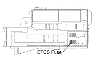
INSPECT FUSE (ETCS)
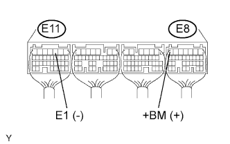
CHECK ECM (+BM VOLTAGE)
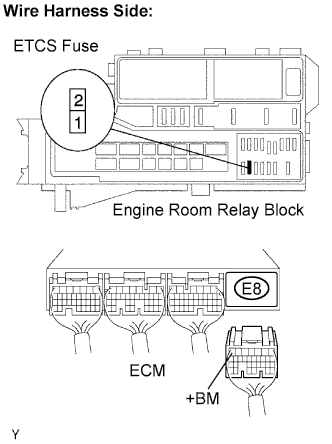
CHECK HARNESS AND CONNECTOR (ETCS FUSE - ECM AND BATTERY)
DTC P2118/89 Throttle Actuator Control Motor Current Range / Performance |
DESCRIPTION
The Electronic Throttle Control System (ETCS) has a dedicated power supply circuit, whose voltage (+BM) is monitored. When the voltage is low (less than 4 V), the ECM concludes that the ETCS has a fault, and the current to the throttle control motor is cut.When the voltage becomes unstable, the ETCS condition itself becomes unstable. For this reason, when the voltage is low, the current to the motor is cut. If repairs are made and the system has returned to normal, turn the ignition switch OFF. The ECM then allows current to flow to the actuator and the motor can be restarted.- HINT:
- This ETCS does not use a throttle cable.
DTC No.
| DTC Detection Condition
| Trouble Area
|
P2118/89
| Open in ETCS power source circuit
| - Open in ETCS power source circuit
- ETCS fuse
- ECM
|
MONITOR DESCRIPTION
The ECM monitors the battery supply voltage applied to the throttle actuator.When the power supply voltage (+BM) drops below 4 V for 0.8 seconds or more, the ECM interprets this as an open in the power supply circuit (+BM). The ECM illuminates the MIL and sets the DTC.This monitor runs for 5 seconds (the first 5 seconds of engine idle) after the engine is started.
FAIL-SAFE
If the ETCS is malfunctioning, the ECM cuts off the current to the throttle actuator. The throttle control valve returns to a predetermined throttle position (approximately 6.5°) by the force of the return spring. Then, required engine power is calculated using the ignition timing and accelerator pedal position. The engine is controlled by intermittent fuel cut.If the accelerator pedal is depressed firmly and slowly, the vehicle can be driven at minimum speed. If the accelerator pedal is depressed quickly, the vehicle may speed up and slow down erratically.
WIRING DIAGRAM
Refer to DTC P2102/41 (Toyota Fortuner RM000000ZQQ006X_04.html).
INSPECTION PROCEDURE
- HINT:
- Read freeze frame data using the intelligent tester. Freeze frame data records the engine conditions when malfunctions are detected. When troubleshooting, freeze frame data can help determine if the vehicle was moving or stationary, if the engine was warmed up or not, if the air-fuel ratio was lean or rich, and other data from the time the malfunction occurred.
Remove the ETCS fuse from the engine room relay block.
Measure the resistance of the fuse.
- Standard resistance:
- Below 1 Ω
| | CHECK FOR SHORT IN ALL HARNESSES AND COMPONENTS CONNECTED TO FUSE |
|
|
| 2.CHECK ECM (+BM VOLTAGE) |
Measure the voltage of the ECM connectors.
- Standard voltage:
Tester Connection
| Specified Condition
|
E8-7 (+BM) - E11-3 (E1)
| 9 to 14 V
|
| | CHECK FOR INTERMITTENT PROBLEMS |
|
|
| 3.CHECK HARNESS AND CONNECTOR (ETCS FUSE - ECM AND BATTERY) |
Remove the ETCS fuse from the engine room relay block.
Disconnect the E8 ECM connector.
Disconnect the cable from the positive (+) battery terminal.
Measure the resistance of the wire harness side connectors.
- Standard resistance:
Tester Connection
| Specified Condition
|
R/B ETCS fuse terminal 2 - E8-7 (+BM)
| Below 1 Ω
|
R/B ETCS fuse terminal 2 or E8-7 (+BM) - Body ground
| 10 kΩ or higher
|
Positive (+) battery cable - R/B ETCS fuse terminal 1
| Below 1 Ω
|
Positive (+) battery cable or R/B ETCS fuse terminal 1 - Body ground
| 10 kΩ or higher
|
| | REPAIR OR REPLACE HARNESS OR CONNECTOR |
|
|