Sfi System -- Data List / Active Test |
| READ DATA LIST |
- HINT:
- Using the intelligent tester's Data List allows switch, sensor, actuator, and other item values to be read without removing any parts. Reading the Data List early in troubleshooting is one way to save time.
- NOTICE:
- In the table below, the values listed under "Normal Condition" are reference values. Do not depend solely on these reference values when deciding whether a part is faulty or not.
Warm up the engine.
Turn the ignition switch OFF.
Connect the intelligent tester to the DLC3.
Turn the ignition switch ON.
Turn the intelligent tester ON.
Enter the following menus: Powertrain / Engine and ECT / Data List.
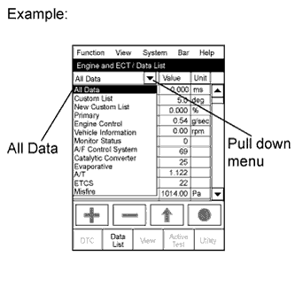
- HINT:
- To display the entire Data List, press the pull down menu button next to Primary. Then select All Data.
Read the Data List on the tester's screen.
Tester Display Measurement Item/Range Normal Condition Diagnostic Note Injector Injection period of the No. 1 cylinder/
Min.: 0 ms, Max.: 32.64 msIdling: 1 to 3 ms - IGN Advance Ignition timing advance for No. 1 cylinder/
Min.: -64°, Max.: 63.5°Idling: BTDC 0 to 20° - Calculate Load ECM calculated load/
Min.: 0%, Max.: 100%- Idling: 10 to 30%
- Running without load (2,500 rpm): 10 to 40%
- MAF Air flow rate from MAF meter/
Min.: 0 g/sec., Max.: 665.35 g/sec.- Idling:
1 to 4 g/sec. - Running without load (2,500 rpm):
4 to 15 g/sec.
If the value is approximately 0.0 g/sec.: - Mass air flow meter power source circuit is open
- VG circuit is open or shorted
- E2G circuit is open
Engine Speed Engine speed/
Min.: 0 rpm, Max.: 16,383.75 rpmIdling: 600 to 700 rpm - Vehicle Speed Vehicle speed/
Min.: 0 km/h, Max.: 255 km/hActual vehicle speed Speed indicated on speedometer Coolant Temp Engine coolant temperature/
Min.: -40°C (-40°F)
Max.: 140°C (284°F)After warming up the engine:
80 to 95°C (176 to 203°F)- If the value is -40°C (-40°F): sensor circuit is open
- If the value is 140°C (284°F): sensor circuit is shorted
Intake Air Intake air temperature/
Min.: -40°C (-40°F)
Max.: 140°C (284°F)Equivalent to ambient air temperature: 50°C (122°F) or less - If the value is -40°C (-40°F): sensor circuit is open
- If the value is 140°C (284°F): sensor circuit is shorted
Air-Fuel Ratio Air-fuel ratio/
Min.: 0, Max.: 1.999Idling: 0.8 to 1.2 - Purge Density Lean Value* Learning value of purge density/
Min.: -50%, Max.: 350%Idling: -25 to 1% Service data Purge Flow* Purge flow/
Min.: 0%, Max.: 102.4%Idling: 0 to 6% - Knock Correct Learn Value Correction learning value of knocking/
Min.: -64°CA, Max.: 1,984°CA0 to 18.5°CA
Driving: 70 km/h (44 mph)Service data Knock Feedback Value Feedback value of knocking/
Min.: -64°CA, Max.: 1,984°CA-20 to 0°CA
Driving: 70 km/h (44 mph)Service data Accelerator Position No. 1 Absolute accelerator pedal position No. 1/
Min.: 0%, Max.: 100%10 to 22%: accelerator pedal is released
54 to 86%: accelerator pedal is fully depressed- Accelerator Position No. 2 Absolute accelerator pedal position No. 2/
Min.: 0%, Max.: 100%12 to 42%: accelerator pedal is released
66 to 98%: accelerator pedal is fully depressed- Accelerator Position No. 1 Accelerator pedal position sensor No. 1 output voltage/
Min.: 0 V, Max.: 4.98 V- ETCS freeze data Accelerator Position No. 2 Accelerator pedal position sensor No. 2 output voltage/
Min.: 0 V, Max.: 4.98 V- ETCS freeze data Accelerator Position No. 1 Accelerator pedal position sensor No. 1 output voltage/
Min.: 0 V, Max.: 5 V- Accelerator pedal released:
0.5 to 1.1 V - Accelerator pedal depressed:
2.6 to 4.5 V
- Accelerator Position No. 2 Accelerator pedal position sensor No. 2 output voltage/
Min.: 0 V, Max.: 5 V- Accelerator pedal released:
1.2 to 2.0 V - Accelerator pedal depressed:
3.4 to 5.3 V
- Accelerator Idle Position Whether or not accelerator pedal position sensor is detecting idle/
ON or OFFIdling: ON
(inspection mode)- Throttle Fully Close Learn Throttle fully closed (learned value)/
Min.: 0 V, Max.: 5 V0.4 to 0.8 V - Accel Fully Close #1 (AD) Accelerator fully closed value No. 1 (AD)/
Min.: 0 V, Max.: 4.9804 V- ETCS service data Accel Fully Close Learn #1 Accelerator fully closed learning value No. 1/
Min.: 0°, Max.: 124.512°- ETCS service data Accel Fully Close Learn #2 Accelerator fully closed learning value No. 2/
Min.: 0°, Max.: 124.512°- ETCS service data Fail Safe Drive Whether or not fail-safe function is executed/ ON or OFF ETCS has failed: ON - Fail Safe Drive (Main CPU) Whether or not fail-safe function is executed/ ON or OFF ETCS has failed: ON - ST1 Brake pedal/ ON or OFF Released: ON
Depressed: OFF- System Guard System guard/
ON or OFF- ETCS service data Open Side Malfunction Open side malfunction/
ON or OFF- ETCS service data Throttle Position Absolute throttle position sensor/
Min.: 0%, Max.: 100%- Throttle fully closed: 10 to 22%
- Throttle fully open: 66 to 98%
Read the value with intrusive operation (Active Test) Throttle Idle Position Whether or not throttle position sensor is detecting idle/
ON or OFFIdling: ON
(inspection mode)- Throttle Require Position Throttle requirement position/
Min.: 0 V, Max.: 5 VIdling: 0.4 to 4.5 V
(Inspection mode)- Throttle Sensor Position Throttle sensor positioning/
Min.: 0%, Max.: 100%Idling 0 to 10%
(Inspection mode)Calculated value based on VTA1 Throttle Sensor Position #2 Throttle sensor positioning #2/
Min.: 0%, Max.: 100%- Calculated value based on VTA2 Throttle Position No. 1 Throttle position sensor No. 1
output voltage/
Min.: 0 V, Max.: 4.98 V- ETCS service data Throttle Position No. 2 Throttle position sensor No. 2 output voltage/ Min.: 0 V, Max.: 4.98 V - ETCS service data Throttle Position No. 1 Throttle position No. 1/
Min.: 0 V, Max.: 5 V- Throttle fully closed:
0.5 to 1.2 V - Throttle fully open:
3.2 to 4.8 V
- Throttle Position No. 2 Throttle position No. 2/
Min.: 0 V, Max.: 5 V- Throttle fully closed: 2.1 to 3.1 V
- Throttle fully open: 4.6 to 5.5 V
Read the value with intrusive operation (Active Test) Throttle Position Command Throttle position command value/
Min.: 0 V, Max.: 4.9804 V0.5 to 4.8 V ETCS service data Throttle Sens Open Pos #1 Throttle sensor opener position No. 1/ Min.: 0, Max.: 4.9804 V 0.6 to 0.9 V ETCS service data Throttle Sens Open Pos #2 Throttle sensor opener position No. 2/ Min.: 0, Max.: 4.9804 V 2.2 to 2.6 V ETCS service data Throttle Sens Open #1 (AD) Throttle sensor opener position No. 1 (AD)/
Min.: 0 V, Max.: 4.9804 V0.6 to 0.9 V ETCS service data Throttle Motor Whether or not throttle motor control is permitted/ ON or OFF Idling: ON
(Inspection mode)Read the value with the ignition switch ON (Do not start engine) Throttle Motor Current Throttle motor current/
Min.: 0 A, Max.: 80 AIdling: 0 to 40 A
(Inspection mode)- Throttle Motor Throttle motor/
Min.: 0%, Max.: 100%Idling: 0.5 to 40%
(Inspection mode)- Throttle Motor Current Throttle motor current/
Min.: 0 A, Max.: 19.92 AIdling: 0 to 3.0 A - Throttle Motor Open Duty Throttle motor opening duty ratio/
Min.: 0%, Max.: 100%During idling: 0 to 40% When accelerator pedal is depressed, duty ratio is increased Throttle Motor Close Duty Throttle motor closed duty ratio/
Min.: 0%, Max.: 100%During idling: 0 to 40% When accelerator pedal is released quickly, duty ratio is increased Throttle Motor Duty (Open) Throttle motor duty ratio (open)/
Min.: 0%, Max.: 100%- ETCS service data Throttle Motor Duty (Close) Throttle motor duty ratio (close)/
Min.: 0%, Max.: 100%- ETCS service data O2S B1 S1* Heated oxygen sensor output voltage for bank 1 sensor 1/
Min.: 0 V, Max.: 1.275 VDriving 70 km/h (44 mph): 0 to 1.0 V Performing Control the Injection Volume function of Active Test enables technician to check output voltage of sensor Short FT #1* Short-term fuel trim of bank 1/
Min.: -100%, Max.: 99.2%-20 to 20% Short-term fuel compensation used to maintain air-fuel ratio at stoichiometric air-fuel ratio Long FT #1* Long-term fuel term of bank 1/
Min.: -100%, Max.: 99.2%-20 to 20% Overall fuel compensation carried out in long-term to compensate continual deviation of short-term fuel trim from central value Fuel System Status (Bank 1)* Fuel system status (Bank 1) /
OL, CL, OL DRIVE, OL FAULT or CL FAULTIdling after warming up: CL
(Inspection mode)- OL (Open Loop): Has not yet satisfied conditions to go closed loop
- CL (Closed Loop): Using heated oxygen sensor(s) as feedback for fuel control.
- OL DRIVE: Open loop due to driving conditions (fuel enrichment)
- OL FAULT: Open loop due to detected system fault
- CL FAULT: Closed loop but heated oxygen sensor which is used for fuel control is malfunctioning
O2FT B1 S1* Short-term fuel trim associated with bank 1 sensor 1/
Min.: -100%, Max.: 99.2%-20 to 20% Same as Short FT #1 Initial Engine Coolant Temp Initial engine coolant temperature/
Min.: -40°C, Max.: 120°CClose to ambient temperature Service data Initial Intake Air Temp Initial intake air temperature/
Min.: -40°C, Max.: 120°CClose to ambient temperature Service data Injection Volume (Cylinder 1) Injection volume (cylinder 1)/
Min.: 0 ml, Max.: 2.048 ml0 to 0.5 ml Quantity of fuel injection volume for 10 times Starter Signal Starter signal/ ON or OFF ON: Cranking - Power Steering Switch Power steering signal/ ON or OFF ON: Power steering operation - Power Steering Signal Power steering signal/ ON or OFF ON: When steering wheel first turned after ignition switch turned to ON This signal status usually ON until ignition switch turned to OFF Closed Throttle Position SW Closed throttle position switch (idle switch)/ ON or OFF ON: throttle valve is closed - A/C Signal A/C Signal/ ON or OFF ON: A/C switch is turned ON - Electrical Load Signal Electrical load signal/ ON or OFF ON: headlights or defogger is turned ON - Stop Light Switch Stop light switch/ ON or OFF ON: brake pedal is depressed - ETCS Actuator Power Whether or not electronic throttle control system power is inputted/
ON or OFFIdling: ON
(inspection mode)- +BM Voltage +BM voltage/
Min.: 0 V, Max.: 19.922 VIdling: 10 to 15 V ETCS service data Battery Voltage Battery voltage/
Min.: 0 V, Max.: 65.535 VIdling: 9 to 14 V
(Inspection mode)- Actuator Power Supply Actuator power supply/
ON or OFFIdling ON
(Inspection mode)ETCS service data Atmosphere Pressure Atmosphere pressure/
Min.: 0 kPa, Max.: 150 kPa- - ACT VSV A/C cut status for Active Test/
ON or OFF- Active Test support data EVAP Purge VSV VSV status for EVAP control/
ON or OFF- Active Test support data Fuel Pump/Speed Status Fuel pump/speed status/
ON or OFFIdling: ON
(Inspection mode)- VVT Control Status VVT control status/
ON or OFF- Support for VVT Active Test TC and TE1 TC and TE1 terminal of DLC3/
ON or OFF- - VVT Aim Angle (Bank 1) VVT aim angle (bank 1)/
Min.: 0%, Max.: 100%Idling: 0% VVT duty signal value during forcible operation VVT Change Angle (Bank 1) VVT change angle/
Min.: 0°FR, Max.: 60°FRIdling: 0 to 5°FR Displacement angle during forcible operation VVT OCV Duty (Bank 1) VVT OCV operation duty/
Min.: 0%, Max.: 100%Idling: 0% Requested duty valve for forcible operation Idle Fuel Cut Fuel cut idle/
ON or OFFFuel cut operation: ON Fuel cut idle ON when throttle valve fully closed and engine speed is over 2,800 rpm FC TAU Fuel cut TAU: Fuel cut during very light load/
ON or OFFFuel cut operating: ON The fuel cut is being performed under very light load to prevent the engine combustion from becoming incomplete #Codes #Codes/
Min.: 0, Max.: 255- Number of detected DTC Check Mode Check mode/ ON or OFF Check mode ON: ON Toyota Fortuner RM000000ZPX007X.html SPD Test Check mode result for vehicle speed sensor/
0: COMPL, 1: INCOMPL- - MIL MIL status/ ON or OFF MIL ON: ON - Engine Run Time Engine run time/
Min.: 0 seconds,
Max.: 65,535 secondsTime after engine start Service data Time after DTC Cleared Time after DTC cleared/
Min.: 0 minutes,
Max.: 65,535 minutesEquivalent to time after DTC was erased - Distance from DTC Cleared Distance from DTC cleared/
Min.: 0 km, Max.: 65,535 kmEquivalent to drive distance after DTCs were erased - Warm-up Cycle Cleared DTC Warm-up cycle after DTC cleared/
Min.: 0, Max.: 255- Number of warm-up cycles after DTC is cleared Model Code Model code - Identifying the model code:
TGN###Engine Type Engine type - Identifying the engine type:
2TR-FECylinder Number Number of cylinders/
Min.: 0, Max.: 255- Identifying number of cylinders:
4Transmission Type Transmission type - Identifying the transmission type:
MTDestination Destination - Identifying the destination:
WModel Year Model year/
Min.: 1900, Max.: 2155- Identifying the model year:
200#System Identification System identification - Identifying the engine system:
GASLIN (gasoline engine)Number of Emission DTC Number of emission DTCs - - - HINT:
- Normal Condition: If no conditions are specifically stated for "Idling", the shift lever is on neutral, the A/C switch is OFF and all accessory switches are OFF.
- *: for Unleaded Gasoline Specification Vehicle.
- Idling: 10 to 30%
 |
| PERFORM ACTIVE TEST |
- HINT:
- Performing the intelligent tester's Active Test allows relay, VSV, actuator and other items to be operated without removing any parts. Performing the Active Test early in troubleshooting is one way to save time.
- The Data List can be displayed during the Active Test.
Warm up the engine.
Turn the ignition switch OFF.
Connect the intelligent tester to the DLC3.
Turn the ignition switch ON.
Turn the intelligent tester ON.
Enter the following menus: Powertrain / Engine and ECT / Active Test.
According to the display on the tester, perform the Active Test.
Tester Display Test Part Control Range Diagnostic Note Control the Injection Volume Control injection volume
(Engine speed: 3,000 rpm or less)Min.: -12.5%, Max.: 24.8% - All injectors are tested at once
- Injection volume is gradually changed between -12.5% and 24.8%
Control the A/C Cut Signal Control A/C cut signal ON or OFF - Activate the VSV for EVAP Control* Activate purge VSV control ON or OFF - Control the Fuel Pump / Speed Control fuel pump ON or OFF Engine is stopped Activate the VVT System (Bank 1) Activate VVT system (Bank 1) ON or OFF - ON: Rough idle or engine stall
- OFF: Normal engine speed
- Vehicle is stopped
- Engine idling
Connect the TC and TE1 Connect TC and TE1 ON or OFF - Control the Idle Fuel Cut Prohibit Control idle fuel cut prohibition ON or OFF During idling Control the ETCS Open/Close Slow Speed Control the ETCS opening/closing slow speed Open or Close Test possible when following conditions met: - Ignition switch ON
- Engine is stopped
- Accelerator pedal is fully depressed
Control the ETCS Open/Close Fast Speed Control the ETCS opening/closing fast speed Open or Close Test possible when following conditions met: - Ignition switch ON
- Engine is stopped
- Accelerator pedal is fully depressed
Control the Cylinder #1 Fuel Cut Control the cylinder #1 fuel cut ON or OFF Cylinder No. 1 fuel cut for power balance - Vehicle is stopped
- Engine idling
Control the Cylinder #2 Fuel Cut Control the cylinder #2 fuel cut ON or OFF Cylinder No. 2 fuel cut for power balance - Vehicle is stopped
- Engine idling
Control the Cylinder #3 Fuel Cut Control the cylinder #3 fuel cut ON or OFF Cylinder No. 3 fuel cut for power balance - Vehicle is stopped
- Engine idling
Control the Cylinder #4 Fuel Cut Control the cylinder #4 fuel cut ON or OFF Cylinder No. 4 fuel cut for power balance - Vehicle is stopped
- Engine idling
Control the VVT linear (bank 1) Control the VVT (bank 1) Min.: -128%, Max.: 127% - - HINT:
- *: for Unleaded Gasoline Specification Vehicle.
- All injectors are tested at once