Engine Immobiliser System Power Source Circuit
DESCRIPTION
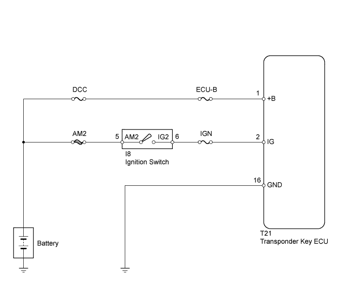
WIRING DIAGRAM
INSPECTION PROCEDURE
INSPECT FUSE (ECU-B, DCC, IGN)
INSPECT IGNITION SWITCH ASSEMBLY
CHECK WIRE HARNESS (TRANSPONDER KEY ECU - BATTERY AND BODY GROUND)
ENGINE IMMOBILISER SYSTEM - Power Source Circuit |
DESCRIPTION
This circuit provides power to operate the transponder key ECU.
WIRING DIAGRAM
INSPECTION PROCEDURE
| 1.INSPECT FUSE (ECU-B, DCC, IGN) |
Remove the ECU-B and DCC fuses from the engine room relay block.
Remove the IGN fuse from the instrument panel junction block.
Measure the resistance of the fuses.
- Standard resistance:
- Below 1 Ω
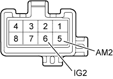
| 2.INSPECT IGNITION SWITCH ASSEMBLY |
Remove the ignition switch.
Measure the resistance of the switch.
- Standard resistance:
Tester Connection
| Switch Condition
| Specified Condition
|
5 (AM2) - 6 (IG2)
| LOCK, ACC
| 10 kΩ or higher
|
ON, START
| Below 1 Ω
|
| | REPLACE IGNITION SWITCH ASSEMBLY |
|
|
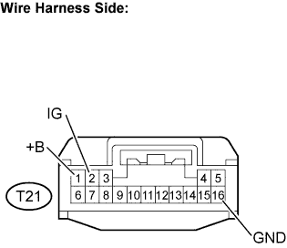
| 3.CHECK WIRE HARNESS (TRANSPONDER KEY ECU - BATTERY AND BODY GROUND) |
Disconnect the T21 ECU connector.
Measure the resistance and voltage of the wire harness side connector.
- Standard resistance:
Tester Connection
| Condition
| Specified Condition
|
T21-16 (GND) - Body ground
| Always
| Below 1 Ω
|
- Standard voltage:
Tester Connection
| Condition
| Specified Condition
|
T21-1 (+B) - Body ground
| Always
| 10 to 14 V
|
T21-2 (IG) - Body ground
| Ignition switch OFF
| Below 1 V
|
Ignition switch ON
| 10 to 14 V
|
| | REPAIR OR REPLACE HARNESS OR CONNECTOR |
|
|
| OK |
|
|
|
| REPLACE TRANSPONDER KEY ECU |
|