Engine Immobiliser System -- Terminals Of Ecu |
| CHECK TRANSPONDER KEY AMPLIFIER |

Disconnect the T20 amplifier connector.
Measure the resistance of the wire harness side connector.
Symbols (Terminal No.) Wiring Color Terminal Description Condition Specified Condition AGND (T20-7) - Body ground L-O - Body ground Ground Always Below 1 Ω - If the result is not as specified, there may be a malfunction on the wire harness side.
- If the result is not as specified, there may be a malfunction on the wire harness side.
Reconnect the T20 amplifier connector.
Measure the resistance and voltage of the connector.
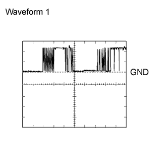
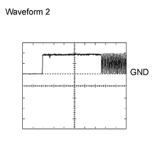
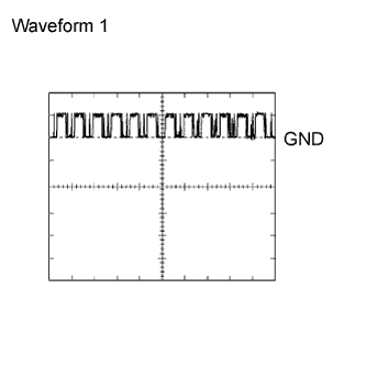
Symbols (Terminal No.) Wiring Color Terminal Description Condition Specified Condition AGND (T20-7) - Body ground L-O - Body ground Ground Always Below 1 Ω VC5 (T20-1) - AGND (T20-7) L - L-O Power source No key in ignition key cylinder Below 1 V Key inserted 4.6 to 5.4 V CODE (T20-4) - AGND (T20-7) L-Y - L-O Demodulated signal of key code data No key in ignition key cylinder Below 1 V Key inserted Pulse generation (see waveform 1) TXCT (T20-5) - AGND (T20-7) L-B - L-O Key code output signal No key in ignition key cylinder Below 1 V Key inserted Pulse generation (see waveform 2) - If the result is not as specified, the amplifier may have a malfunction.
- If the result is not as specified, the amplifier may have a malfunction.
Using an oscilloscope, check waveform 1.
Waveform 1 (Reference): Item Content Symbols (Terminal No.) CODE (T20-4) - AGND (T20-7) Tool Setting 2 V/DIV., 20 msec./DIV. Condition Key inserted Using an oscilloscope, check waveform 2.
Waveform 2 (Reference): Item Content Symbols (Terminal No.) TXCT (T20-5) - AGND (T20-7) Tool Setting 2 V/DIV., 20 msec./DIV. Condition Key inserted
 |
 |
| CHECK TRANSPONDER KEY ECU |

Disconnect the T21 ECU connector.
Measure the voltage and resistance of the wire harness side connector.
Symbols (Terminal No.) Wiring Color Terminal Description Condition Specified Condition AGND (T21-5) - Body ground L-O - Body ground Ground Always Below 1 Ω GND (T21-16) - Body ground G - Body ground Ground Always Below 1 Ω +B (T21-1) - GND (T21-16) L-Y - G Power source supply Always 10 to 14 V IG (T21-2) - GND (T21-16) B-O - G Ignition power supply Ignition switch OFF Below 1 V Ignition switch ON 10 to 14 V KSW (T21-3) - GND (T21-16) BR - G Unlock warning switch No key in ignition key cylinder 10 kΩ or higher Key inserted Below 1 Ω - If the result is not as specified, there may be a malfunction on the wire harness side.
- If the result is not as specified, there may be a malfunction on the wire harness side.
Reconnect the T21 ECU connector.
Measure the voltage of the connector.
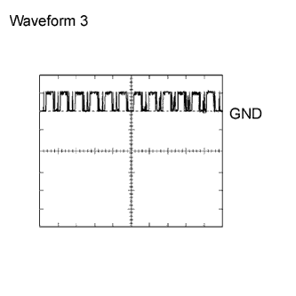
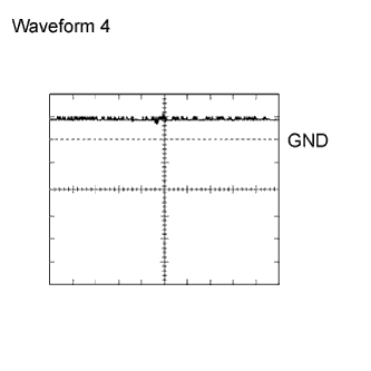
Symbols (Terminal No.) Wiring Color Terminal Description Condition Specified Condition VC5 (T21-14) - AGND (T21-5) L - L-O Power source of transponder key amplifier No key in ignition key cylinder Below 1 V Key is inserted 4.6 to 5.4 V CODE (T21-15) - AGND (T21-5) L-Y - L-O Transponder key amplifier communication signal No key in ignition key cylinder Below 1 V Key is inserted Pulse generation (see waveform 1) TXCT (T21-4) - AGND (T21-5) L-B - L-O Transponder key amplifier communication signal No key in ignition key cylinder Below 1 V Key is inserted Pulse generation (see waveform 2) EFIO (T21-13) - E (T21-11) Y-G - W-B ECM output signal Ignition switch OFF Below 1 V Ignition switch ON Pulse generation (see waveform 3) EFII (T21-12) - E (T21-11) Y-B - W-B ECM input signal Ignition switch OFF Below 1 V Ignition switch ON Pulse generation (see waveform 4) - If the result is not as specified, the ECU may have a malfunction.
- If the result is not as specified, the ECU may have a malfunction.
Using an oscilloscope, check waveform 1.
Waveform 1 (Reference): Item Content Symbols (Terminal No.) CODE (T21-15) - AGND (T21-5) Tool Setting 2 V/DIV., 20 msec./DIV. Condition Key inserted Using an oscilloscope, check waveform 2.
Waveform 2 (Reference): Item Content Symbols (Terminal No.) TXCT (T21-4) - AGND (T21-5) Tool Setting 2 V/DIV., 20 msec./DIV Condition Key inserted Using an oscilloscope, check waveform 3.
Waveform 3 (Reference): Item Content Symbols (Terminal No.) EFIO (T21-13) - EOM (T21-11) Tool Setting 10 V/DIV., 100 msec./DIV. Condition Ignition switch ON Using an oscilloscope, check waveform 4.
Waveform 4 (Reference): Item Content Symbols (Terminal No.) EFII (T21-12) - EOM (T21-11) Tool Setting 10 V/DIV., 100 msec./DIV. Condition Ignition switch ON
|
|
 |
 |
| CHECK ECM (1GR-FE) |

Measure the voltage and resistance of the connectors.
Symbols (Terminal No.) Wiring Color Terminal Description Condition Specified Condition IMI (E13-16) - EOM (E13-35) Y-G - W-B Transponder key ECU input signal Ignition switch OFF Below 1 V Ignition switch ON Pulse generation (see waveform 1) IMO (E13-15) - EOM (E13-35) Y-B -W-B Transponder key ECU output signal Ignition switch OFF Below 1 V Ignition switch ON Pulse generation (see waveform 2) E01 (E15-7) - Body ground W-B - Body ground Ground Always Below 1 Ω E02 (E15-6) - Body ground W-B - Body ground Ground Always Below 1 Ω E1 (E17-21) - Body ground BR - Body ground Ground Always Below 1 Ω - If the result is not as specified, the ECM may have a malfunction.
- If the result is not as specified, the ECM may have a malfunction.
Using an oscilloscope, check waveform 1.
Waveform 1 (Reference): Item Content Symbols (Terminal No.) IMI (E13-16) - EOM (E13-35) Tool Setting 10 V/DIV., 100 msec./DIV. Condition Ignition switch ON Using an oscilloscope, check waveform 2.
Waveform 2 (Reference): Item Content Symbols (Terminal No.) IMO (E13-15) - EOM (E13-35) Tool Setting 10 V/DIV., 100 msec./DIV. Condition Ignition switch ON
 |
 |
| CHECK ECM (1KD-FTV) |
Measure the voltage and resistance of the connectors.
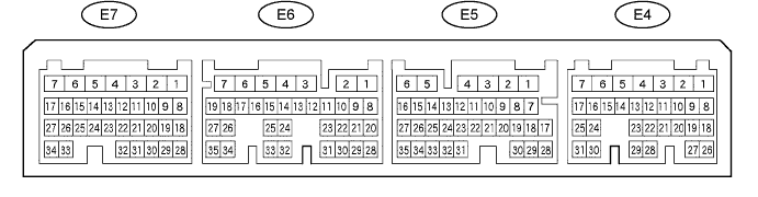
Symbols (Terminal No.) Wiring Color Terminal Description Condition Specified Condition IMI (E5-30) - EOM (E4-16) Y-G - W-B Transponder key ECU input signal Ignition switch OFF Below 1 V Ignition switch ON Pulse generation (see waveform 1) IMO (E5-29) - EOM (E4-16) Y-B -W-B Transponder key ECU output signal Ignition switch OFF Below 1 V Ignition switch ON Pulse generation (see waveform 2) E01 (E7-7) - Body ground W-B - Body ground Ground Always Below 1 Ω E02 (E7-6) - Body ground W - Body ground Ground Always Below 1 Ω E1 (E6-7) - Body ground BR - Body ground Ground Always Below 1 Ω - If the result is not as specified, the ECM may have a malfunction.
- If the result is not as specified, the ECM may have a malfunction.
Using an oscilloscope, check waveform 1.
Waveform 1 (Reference): Item Content Symbols (Terminal No.) IMI (E5-30) - EOM (E4-16) Tool Setting 10 V/DIV., 100 msec./DIV. Condition Ignition switch ON Using an oscilloscope, check waveform 2.
Waveform 2 (Reference): Item Content Symbols (Terminal No.) IMI (E6-30) - EOM (E4-16) Tool Setting 10 V/DIV., 100 msec./DIV. Condition Ignition switch ON
|
|