Airbag System Tc And Cg Terminal Circuit
DESCRIPTION
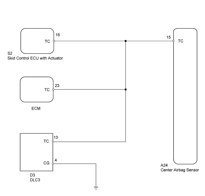
WIRING DIAGRAM
INSPECTION PROCEDURE
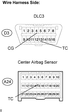
CHECK WIRE HARNESS (DLC3 - CENTER AIRBAG SENSOR AND BODY GROUND)
AIRBAG SYSTEM - TC and CG Terminal Circuit |
DESCRIPTION
DTC output mode is set by connecting terminals TC and CG of the DLC3. The DTCs are communicated through SRS warning light blinking patterns.- HINT:
- When one or more of the warning lights blinks continuously, the cause may be a ground short in the wiring of terminal TC of the DLC3 or an internal ground short in each ECU.
WIRING DIAGRAM
INSPECTION PROCEDURE
- CAUTION:
- Be sure to perform the following procedures before troubleshooting to avoid unexpected airbag deployment.
- Turn the ignition switch OFF.
- Disconnect the cable from the negative (-) battery terminal, and wait for at least 90 seconds.
| 1.CHECK WIRE HARNESS (DLC3 - CENTER AIRBAG SENSOR AND BODY GROUND) |
Disconnect the A24 ECU connector.
Measure the resistance of the wire harness side connectors.
- Standard resistance:
Tester Connection
| Specified Condition
|
D3-13 (TC) - A24-15 (TC)
| Below 1 Ω
|
D3-4 (CG) - Body ground
| Below 1 Ω
|
A24-15 (TC) - Body ground
| 1 MΩ or higher
|
| | REPAIR OR REPLACE HARNESS AND CONNECTOR |
|
|
| OK |
|
|
|
| REPLACE CENTER AIRBAG SENSOR ASSEMBLY |
|