Dtc C1249/49 Open In Stop Light Switch Circuit
DESCRIPTION
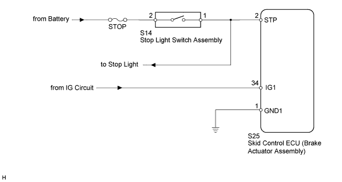
WIRING DIAGRAM
INSPECTION PROCEDURE
CHECK STOP LIGHT OPERATION
INSPECT SKID CONTROL ECU (STP TERMINAL)
INSPECT SKID CONTROL ECU (IG1 TERMINAL)
INSPECT SKID CONTROL ECU (GND1 TERMINAL)
RECONFIRM DTC
INSPECT STOP LIGHT SWITCH (POWER SOURCE TERMINAL)
INSPECT STOP LIGHT SWITCH
CHECK HARNESS AND CONNECTOR (SKID CONTROL ECU - STOP LIGHT SWITCH)
RECONFIRM DTC
DTC C1249/49 Open in Stop Light Switch Circuit |
DESCRIPTION
The skid control ECU (housed in the brake actuator assembly) receives the stop light switch signal and the condition of brake operation.The skid control ECU has an open detection circuit, which outputs this DTC when detecting an open in the stop light switch signal input line or the ground line of the stop light switch circuit with the stop light switch off (brake pedal not depressed).DTC Code
| DTC Detection Condition
| Trouble Area
|
C1249/49
| The IG1 terminal voltage is 9.5 V or more and an open circuit in the stop light switch circuit continues for 0.3 seconds or more.
| - STOP fuse
- Stop light switch
- Stop light switch circuit
- Skid control ECU (Brake actuator assembly)
|
WIRING DIAGRAM
INSPECTION PROCEDURE
- NOTICE:
- When replacing the brake actuator assembly, perform zero point calibration (Toyota Fortuner RM000000XHR02TX.html).
- Inspect the fuses for circuits related to this system before performing the following inspection procedure.
| 1.CHECK STOP LIGHT OPERATION |
Check that the stop light comes on when the brake pedal is depressed, and goes off when the brake pedal is released.
- OK:
Condition
| Illumination Condition
|
Brake pedal depressed
| ON
|
Brake pedal released
| OFF
|
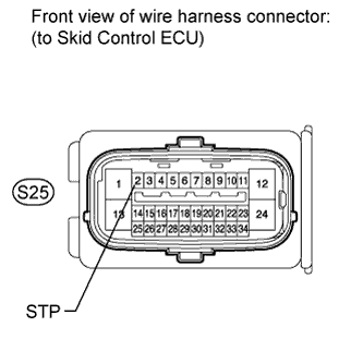
| 2.INSPECT SKID CONTROL ECU (STP TERMINAL) |
Disconnect the skid control ECU connector.
Measure the voltage according to the value(s) in the table below.
- Standard Voltage:
Tester Connection
| Switch Condition
| Specified Condition
|
S25-2 (STP) - Body ground
| Stop light switch ON (Brake pedal depressed)
| 8 to 14 V
|
S25-2 (STP) - Body ground
| Stop light switch OFF (Brake pedal released)
| Below 1.5 V
|
| | REPAIR OR REPLACE HARNESS OR CONNECTOR (STP CIRCUIT) |
|
|
| 3.INSPECT SKID CONTROL ECU (IG1 TERMINAL) |
Disconnect the skid control ECU connector.
Measure the voltage according to the value(s) in the table below.
- Standard Voltage:
Tester Connection
| Switch Condition
| Specified Condition
|
S25-34 (IG1) - Body ground
| Ignition switch ON
| 11 to 14 V
|
| | REPAIR OR REPLACE HARNESS OR CONNECTOR (IG1 CIRCUIT) |
|
|
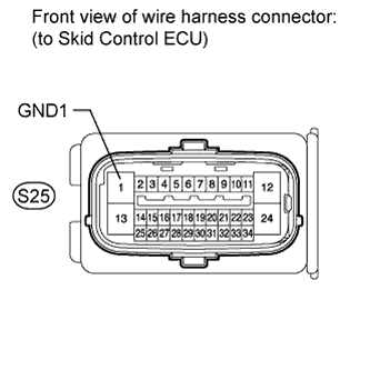
| 4.INSPECT SKID CONTROL ECU (GND1 TERMINAL) |
Disconnect the skid control ECU connector.
Measure the resistance according to the value(s) in the table below.
- Standard Resistance:
Tester Connection
| Condition
| Specified Condition
|
S25-1 (GND1) - Body ground
| Always
| Below 1 Ω
|
| | REPAIR OR REPLACE HARNESS OR CONNECTOR (GND CIRCUIT) |
|
|
Clear the DTC(s) (Toyota Fortuner RM000000XHV09NX.html).
Start the engine.
Depress the brake pedal several times to test the stop light circuit.
Check if the same DTC is recorded (Toyota Fortuner RM000000XHV09NX.html).
ResultResult
| Proceed to
|
DTC not output
| A
|
DTC output
| B
|
- HINT:
- If troubleshooting has been carried out according to the Problem Symptoms Table, refer back to the table and proceed to the next step (Toyota Fortuner RM000000XHN092X.html).
| | REPLACE BRAKE ACTUATOR ASSEMBLY |
|
|
| A |
|
|
|
| USE SIMULATION METHOD TO CHECK |
|
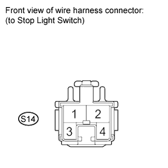
| 6.INSPECT STOP LIGHT SWITCH (POWER SOURCE TERMINAL) |
Disconnect the stop light switch connector.
Measure the voltage according to the value(s) in the table below.
- Standard Voltage:
Tester Connection
| Condition
| Specified Condition
|
S14-2 - Body ground
| Always
| 11 to 14 V
|
| | REPAIR OR REPLACE HARNESS OR CONNECTOR (POWER SOURCE CIRCUIT) |
|
|
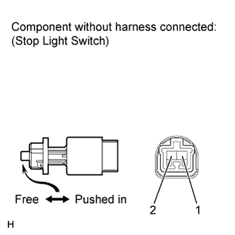
| 7.INSPECT STOP LIGHT SWITCH |
Remove the stop light switch.
Measure the resistance according to the value(s) in the table below.
- Standard Resistance:
Tester Connection
| Switch Condition
| Specified Condition
|
1 - 2
| Switch pin free
| Below 1 Ω
|
1 - 2
| Switch pin pushed in
| 10 kΩ or higher
|
| | REPLACE STOP LIGHT SWITCH |
|
|
| 8.CHECK HARNESS AND CONNECTOR (SKID CONTROL ECU - STOP LIGHT SWITCH) |
Disconnect the stop light switch connector.
Disconnect the skid control ECU connector.
Measure the resistance according to the value(s) in the table below.
- Standard Resistance:
Tester Connection
| Condition
| Specified Condition
|
S25-2 (STP) - S14-1
| Always
| Below 1 Ω
|
S25-2 (STP) - Body ground
| Always
| 10 kΩ or higher
|
| | REPAIR OR REPLACE HARNESS OR CONNECTOR |
|
|
Clear the DTC(s) (Toyota Fortuner RM000000XHV09NX.html).
Start the engine.
Depress the brake pedal several times to test the stop light circuit.
Check if the same DTC is recorded (Toyota Fortuner RM000000XHV09NX.html).
ResultResult
| Proceed to
|
DTC not output
| A
|
DTC output
| B
|
- HINT:
- If troubleshooting has been carried out according to the Problem Symptoms Table, refer back to the table and proceed to the next step (Toyota Fortuner RM000000XHN092X.html).
| | REPLACE BRAKE ACTUATOR ASSEMBLY |
|
|
| A |
|
|
|
| INSPECT LIGHTING SYSTEM (STOP LIGHT CIRCUIT) |
|