Ecd System Air Conditioning Cut Control Circuit
DESCRIPTION
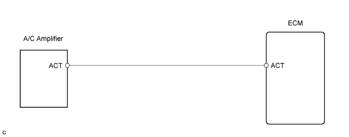
WIRING DIAGRAM
INSPECTION PROCEDURE
When using intelligent tester:
READ VALUE USING INTELLIGENT TESTER (CHECK OPERATION AIR CONDITIONING CUT CONTROL)
INSPECT ECM (ACT VOLTAGE)
CHECK HARNESS AND CONNECTOR (ECM - AIR CONDITIONING AMPLIFIER)
When not using intelligent tester:
CHECK ECM (ACT VOLTAGE)
CHECK HARNESS AND CONNECTOR (ECM - AIR CONDITIONING AMPLIFIER)
ECD SYSTEM - Air Conditioning Cut Control Circuit |
DESCRIPTION
This circuit cuts air conditioning operation during vehicle acceleration in order to increase acceleration performance. During acceleration with the vehicle speed at 30 km/h (19 mph) or less and accelerator pedal opening angle at 45° or more, the A/C magnetic switch is turned off for several seconds.The air conditioning is also controlled by the ECM outputting the engine coolant temperature to A/C amplifier.
WIRING DIAGRAM
INSPECTION PROCEDURE
When using intelligent tester:
| 1.READ VALUE USING INTELLIGENT TESTER (CHECK OPERATION AIR CONDITIONING CUT CONTROL) |
Connect the intelligent tester to the DLC3.
Start the engine and turn the air conditioning switch ON.
- HINT:
- A/C magnetic clutch is turned ON.
Enter the following menus: Powertrain / Engine and ECT / Active Test / A/C Cut SIG.
Check operation of A/C magnetic clutch cut when air conditioning cut control is operated by the intelligent tester.
- OK:
- A/C magnetic clutch is turned OFF.
| | PROCEED TO NEXT CIRCUIT INSPECTION SHOWN IN PROBLEM SYMPTOMS TABLE |
|
|
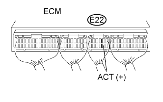
| 2.INSPECT ECM (ACT VOLTAGE) |
Start the engine.
Measure the voltage of the ECM connector.
- Standard voltage:
Tester Connection
| Condition
| Specified Condition
|
E22-8 (ACT) - Body ground
| Engine at idling
| 9 to 14 V
|
E22-8 (ACT) - Body ground
| Ignition switch ON, Engine stopped
| 0 to 3 V
|
| 3.CHECK HARNESS AND CONNECTOR (ECM - AIR CONDITIONING AMPLIFIER) |
Disconnect the A14 A/C amplifier connector.
Disconnect the E22 ECM connector.
Measure the resistance of the wire harness side connectors.
- Standard resistance:
Tester Connection
| Specified Condition
|
A14-2 (ACT)* - E22-8 (ACT)
| Below 1 Ω
|
E22-8 (ACT) - Body ground
| 10 kΩ or higher
|
- HINT:
- *: Terminal arrangement (Toyota Fortuner RM000002HPK000X.html).
| | REPAIR OR REPLACE HARNESS OR CONNECTOR |
|
|
| OK |
|
|
|
| REPLACE AIR CONDITIONING AMPLIFIER |
|
When not using intelligent tester:
| 1.CHECK ECM (ACT VOLTAGE) |
Start the engine.
Measure the voltage of the ECM connector.
- Standard voltage:
Tester Connection
| Condition
| Specified Condition
|
E22-8 (ACT) - Body ground
| Engine at idling
| 9 to 14 V
|
E22-8 (ACT) - Body ground
| Ignition switch ON, Engine stopped
| 0 to 3 V
|
| 2.CHECK HARNESS AND CONNECTOR (ECM - AIR CONDITIONING AMPLIFIER) |
Disconnect the A14 A/C amplifier connector.
Disconnect the E22 ECM connector.
Measure the resistance of the wire harness side connectors.
- Standard resistance:
Tester Connection
| Specified Condition
|
A14-2 (ACT)* - E22-8 (ACT)
| Below 1 Ω
|
E22-8 (ACT) - Body ground
| 10 kΩ or higher
|
- HINT:
- *: Terminal arrangement (Toyota Fortuner RM000002HPK000X.html).
| | REPAIR OR REPLACE HARNESS OR CONNECTOR |
|
|
| OK |
|
|
|
| REPLACE AIR CONDITIONING AMPLIFIER |
|