Dtc P0617 Starter Relay Circuit High
DESCRIPTION
WIRING DIAGRAM
INSPECTION PROCEDURE
READ VALUE USING INTELLIGENT TESTER (STARTER SIGNAL)
INSPECT PARK/NEUTRAL POSITION SWITCH (A/T) OR WIRE HARNESS (ECM - INSTRUMENT PANEL JUNCTION BLOCK)
READ VALUE USING INTELLIGENT TESTER (STARTER SIGNAL)
INSPECT IGNITION SWITCH ASSEMBLY
READ VALUE USING INTELLIGENT TESTER (STARTER SIGNAL)
DTC P0617 Starter Relay Circuit High |
DESCRIPTION
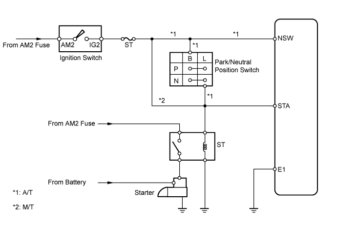
While the engine is being cranked, positive (+) battery voltage is applied to terminal STA of the ECM.If the ECM detects the Starter Control (STA) signal while the vehicle is being driven, it will conclude that there is fault in the starter control circuit. The ECM will turn on the Malfunction Indicator Lamp (MIL) and set a DTC.This monitor runs when the vehicle is driven at 20 km/h (12 mph) for over 20 seconds.DTC No.
| DTC Detection Condition
| Trouble Area
|
P0617
| Following conditions are met for 20 seconds:
- Vehicle speed is greater than 20 km/h (12 mph)
- Engine rpm is greater than 1,000 rpm
- STA signal ON
| - Short in PNP switch (A/T) circuit
- STA signal circuit (M/T)
- PNP switch (A/T)
- Ignition switch
- ECM
|
WIRING DIAGRAM
INSPECTION PROCEDURE
- HINT:
- Read freeze frame data using the intelligent tester. Freeze frame data records the engine conditions when a malfunction is detected. When troubleshooting, freeze frame data can help determine if the vehicle was running or stopped, if the engine was warmed up or not, if the air-fuel ratio was lean or rich, and other data from the time the malfunction occurred.
| 1.READ VALUE USING INTELLIGENT TESTER (STARTER SIGNAL) |
Connect the intelligent tester to the DLC3.
Turn the ignition switch ON and turn the tester ON.
Enter the following menus: Powertrain / Engine and ECT / Data List / Starter SIG.
Confirm the starter signal status when the ignition switch is operated.
- OK:
Ignition Switch Position
| Starter Signal
|
ON
| OFF
|
START
| ON
|
| 2.INSPECT PARK/NEUTRAL POSITION SWITCH (A/T) OR WIRE HARNESS (ECM - INSTRUMENT PANEL JUNCTION BLOCK) |
A/T:
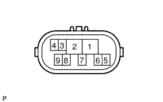
Inspect the Park/Neutral Position (PNP) switch.
(1) Disconnect the N1 switch connector.
(2) Measure the resistance when the shift lever is moved to each position.
- Standard resistance:
Tester Connection
| Shift Lever Position
| Specified Condition
|
4 (B) - 5 (L)
| P
| Below 1 Ω
|
4 (B) - 5 (L)
| N
| Below 1 Ω
|
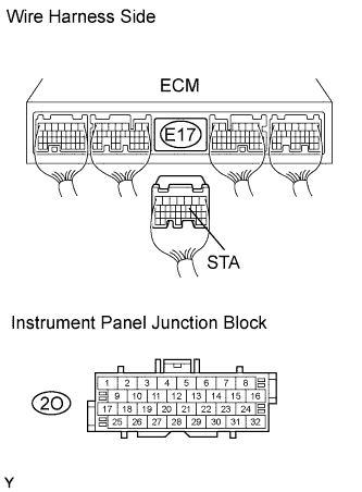
M/T:
Disconnect the E17 ECM connector.
Disconnect the 2O junction block connector.
Measure the resistance of the wire harness side connectors.
- Standard resistance:
Tester Connection
| Specified Condition
|
2O-19 - E17-11 (STA)
| Below 1 Ω
|
2O-19 or E17-11 (STA) - Body ground
| 10 kΩ or higher
|
| | REPLACE PARK/NEUTRAL POSITION SWITCH OR HARNESS AND CONNECTOR |
|
|
| 3.READ VALUE USING INTELLIGENT TESTER (STARTER SIGNAL) |
Connect the intelligent tester to the DLC3.
Turn the ignition switch ON and turn the tester ON.
Enter the following menus: Powertrain / Engine and ECT / Data List / Starter SIG.
Confirm the starter signal status when the ignition switch is operated.
- OK:
Ignition Switch Position
| Starter Signal
|
ON
| OFF
|
START
| ON
|
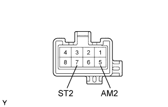
| 4.INSPECT IGNITION SWITCH ASSEMBLY |
Disconnect the I6 ignition switch connector.
Measure the resistance of the ignition switch.
- Standard resistance:
Tester Connection
| Switch Condition
| Specified Condition
|
5 (AM2) - 7 (ST2)
| LOCK
| 10 kΩ or higher
|
5 (AM2) - 7 (ST2)
| START
| Below 1 Ω
|
| | REPLACE IGNITION SWITCH ASSEMBLY |
|
|
| 5.READ VALUE USING INTELLIGENT TESTER (STARTER SIGNAL) |
Connect the intelligent tester to the DLC3.
Turn the ignition switch ON and turn the tester ON.
Enter the following menus: Powertrain / Engine and ECT / Data List / Starter SIG.
Confirm the starter signal status when the ignition switch is operated.
- OK:
Ignition Switch Position
| Starter Signal
|
ON
| OFF
|
START
| ON
|
| | REPAIR OR REPLACE HARNESS AND CONNECTOR |
|
|