Theft Deterrent System Back Door Courtesy Switch Circuit
DESCRIPTION
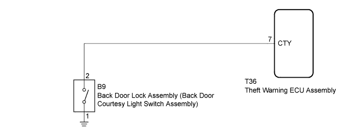
WIRING DIAGRAM
INSPECTION PROCEDURE
INSPECT BACK DOOR LOCK ASSEMBLY (BACK DOOR COURTESY SWITCH)
CHECK HARNESS AND CONNECTOR (BACK DOOR LOCK - THEFT WARNING ECU AND BODY GROUND)
THEFT DETERRENT SYSTEM - Back Door Courtesy Switch Circuit |
DESCRIPTION
The theft warning ECU assembly detects the condition of the back door lock assembly (back door courtesy light switch assembly).
WIRING DIAGRAM
INSPECTION PROCEDURE
| 1.INSPECT BACK DOOR LOCK ASSEMBLY (BACK DOOR COURTESY SWITCH) |
Remove the back door lock assembly (Toyota Fortuner RM000004RY800BX.html).
Text in Illustration*a
| Latch Condition
| *b
| Open-latch
|
*c
| Half-latch
| *d
| Full-latch
|
*e
| Over-latch
| -
| -
|
Measure the resistance according to the value(s) in the table below.
- Standard Resistance:
Tester Connection
| Switch Condition
| Specified Condition
|
1 - 2
| Open-latch (ON)
| Below 1 Ω
|
Half-latch (ON)
| Below 1 Ω
|
Full-latch (OFF)
| 10 kΩ or higher
|
Over-latch (OFF)
| 10 kΩ or higher
|
| 2.CHECK HARNESS AND CONNECTOR (BACK DOOR LOCK - THEFT WARNING ECU AND BODY GROUND) |
Disconnect the B9 back door lock assembly connector.
Disconnect the T36 theft warning ECU assembly connector.
Measure the resistance according to the value(s) in the table below.
- Standard Resistance:
Tester Connection
| Condition
| Specified Condition
|
B9-2 - T36-7 (CTY)
| Always
| Below 1 Ω
|
B9-1 or T36-7 (CTY) - Body ground
| Always
| 10 kΩ or higher
|
B9-1 - Body ground
| Always
| Below 1 Ω
|
| | REPAIR OR REPLACE HARNESS OR CONNECTOR |
|
|