Roof Headlining -- Installation |
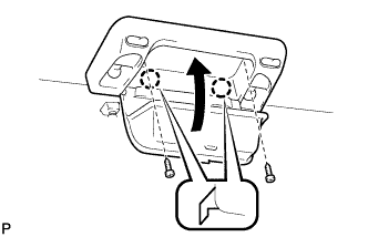
| 1. INSTALL NO. 2 AIR OUTLET REGISTER ASSEMBLY (w/ Rear Cooler) |
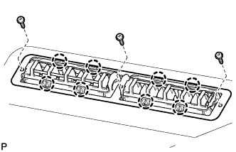 |
Attach the 8 claws to install the bracket and air outlet register.
Install the 3 screws.
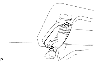
| 2. INSTALL NO. 1 AIR OUTLET REGISTER ASSEMBLY (w/ Rear Cooler) |
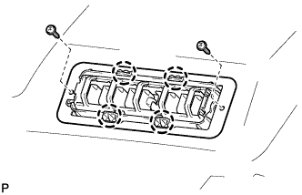 |
- HINT:
- Use the same procedures to install the air outlet register on the other side.
Attach the 4 claws to install the bracket and air outlet register.
Install the 2 screws.
| 3. INSTALL FRONT SIDE RAIL SPACER LH |
Install the side rail spacer.
| 4. INSTALL FRONT SIDE RAIL SPACER RH |
Install the side rail spacer.
| 5. INSTALL SIDE RAIL SPACER REAR LH (for LHD) |
Install the side rail spacer.
| 6. INSTALL REAR SIDE RAIL SPACER RH (for RHD) |
Install the side rail spacer.
| 7. INSTALL REAR NO. 2 SIDE RAIL SPACER LH |
Install the 4 side rail spacers.
| 8. INSTALL REAR NO. 2 SIDE RAIL SPACER RH |
Install the 4 side rail spacers.
| 9. INSTALL REAR NO. 3 SIDE RAIL SPACER LH |
Install the side rail spacer.
| 10. INSTALL REAR NO. 3 SIDE RAIL SPACER RH |
Install the side rail spacer.
| 11. INSTALL NO. 2 ROOF SILENCER PAD |
Install the 3 silencer pads.
| 12. INSTALL ROOF HEADLINING ASSEMBLY (for LHD) |
Install new packing to the roof headlining.
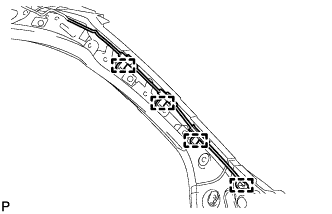
Align the roof wire to the markings, and then install the roof wire with tape.
- NOTICE:
- Attach the roof wire securely.
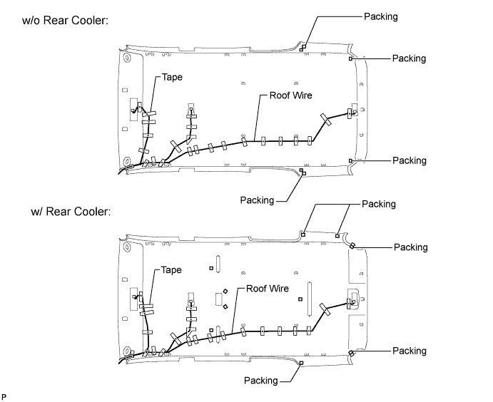
w/o Rear Cooler:
Install the roof headlining with the 9 clips.
 |
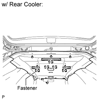
w/ Rear Cooler:
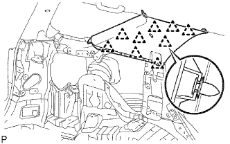
Attach the 5 fasteners to install the roof headlining.
Install the 7 clips.
 |
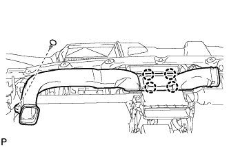
Connect the connector and attach the 4 clamps.
 |
Attach the 4 clamps to the front pillar.
 |
| 13. INSTALL ROOF HEADLINING ASSEMBLY (for RHD) |
Install new packing to the roof headlining.
Align the roof wire to the markings, and then install the roof wire with tape.
- NOTICE:
- Attach the roof wire securely.
w/o Rear Cooler:
Install the roof headlining with the 9 clips.
 |
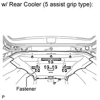
w/ Rear Cooler (5 assist grip type):
Attach the 5 fasteners to install the roof headlining.
Install the 7 clips.
 |
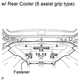
w/ Rear Cooler (6 assist grip type):
Attach the 5 fasteners to install the roof headlining.
Install the 5 clips.
 |
Connect the 2 connectors and attach the 5 clamps.

Attach the 4 clamps to the front pillar.
|
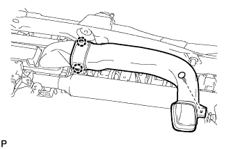
| 14. INSTALL NO. 3 HEATER TO REGISTER DUCT |
 |
Attach the 4 claws to install the duct.
Install the clip.
| 15. INSTALL NO. 1 HEATER TO REGISTER DUCT |
 |
Attach the 2 claws to install the duct.
Install the clip.
| 16. INSTALL NO. 2 HEATER TO REGISTER DUCT |
Install the duct with the 3 clips.

| 17. INSTALL LOWER INSTRUMENT PANEL FINISH PANEL SUB-ASSEMBLY |
 |
Attach the 2 claws and 3 clips to install the panel.
| 18. INSTALL UPPER INSTRUMENT PANEL SUB-ASSEMBLY |
Install the instrument panel sub-assembly (Toyota Fortuner RM000003O2K007X.html).
| 19. INSTALL ASSIST GRIP |
 |
- HINT:
- Use the same procedure to install the other assist grips.
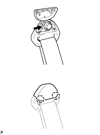
Install the assist grip with the 2 screws.
Attach the 4 claws to close the 2 covers.
 |
| 20. INSTALL VISOR HOLDER LH |
 |
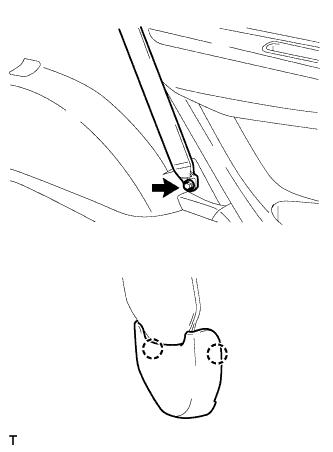
Attach the 2 claws to install the visor holder.
Install the screw.
| 21. INSTALL VISOR HOLDER RH |
- HINT:
- Use the same procedures described for the LH side.
| 22. INSTALL VISOR ASSEMBLY LH |
 |
Install the visor with the 2 screws.
| 23. INSTALL VISOR ASSEMBLY RH |
- HINT:
- Use the same procedures described for the LH side.
| 24. INSTALL NO. 1 ROOM LIGHT ASSEMBLY |
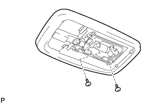 |
Connect the light connector.
Install the room light with the 2 screws.
Attach the 4 claws to install the lens
| 25. INSTALL NO. 2 ROOM LIGHT ASSEMBLY |
Connect the light connector.
|
Install the room light with the 2 screws.
Attach the 4 claws to install the lens
| 26. INSTALL COOLER CONTROL SWITCH ASSEMBLY (w/ Rear Cooler) |
Connect the connector.
Attach the 2 claws shown in the illustration.
 |
Attach the remaining 2 claws to install the control switch.
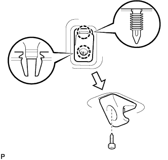
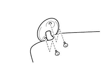
| 27. INSTALL MAP LIGHT ASSEMBLY |
 |
Connect the light connector.
Install the map light as shown in the illustration.
Install the 2 screws.
| 28. INSTALL NO. 1 MAP LIGHT LENS |
 |
Attach the 2 claws to install the map light lens.
| 29. INSTALL NO. 2 MAP LIGHT LENS |
- HINT:
- Use the same procedures described for the No. 1 lens.
| 30. INSTALL INNER UPPER ROOF SIDE GARNISH LH |
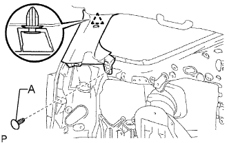 |
Attach the clip to install the roof side garnish.
Install the clip labeled A.
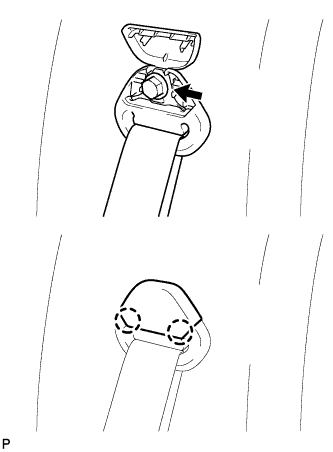
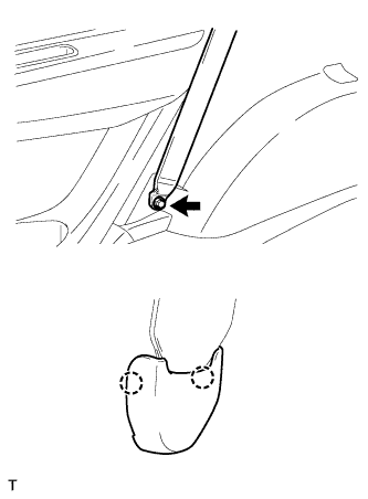
Connect the rear outer No. 2 seat belt shoulder anchor.
Connect the shoulder anchor with the bolt.
- Torque:
- 42 N*m{428 kgf*cm, 31 ft.*lbf}
Attach the 2 claws to close the seat belt anchor cover.
| 31. INSTALL INNER UPPER ROOF SIDE GARNISH RH |
- HINT:
- Use the same procedures described for the LH side.
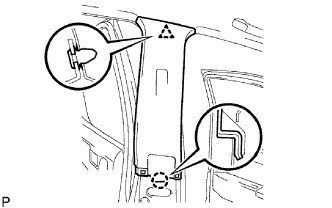
| 32. INSTALL QUARTER PILLAR GARNISH LH |
 |
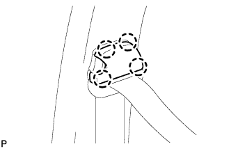
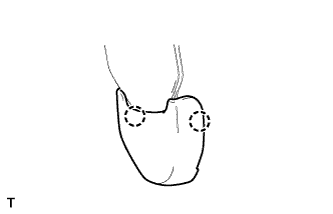
Attach the 9 clips to install the quarter pillar garnish.
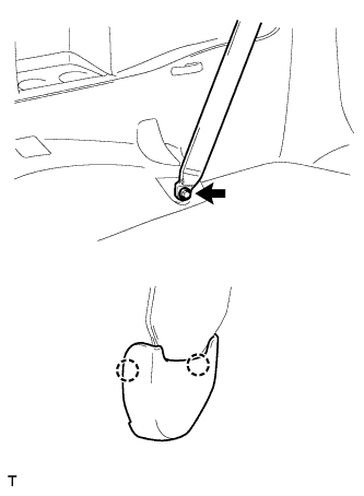
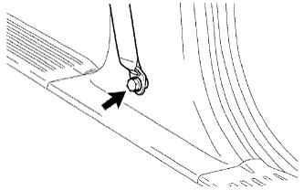
Connect the rear outer No. 1 seat belt shoulder anchor.
Connect the shoulder anchor with the bolt.
- Torque:
- 42 N*m{428 kgf*cm, 31 ft.*lbf}
Attach the 2 claws to close the seat belt anchor cover.
 |
| 33. INSTALL QUARTER PILLAR GARNISH RH |
- HINT:
- Use the same procedures described for the LH side.
| 34. INSTALL POWER POINT SOCKET ASSEMBLY |
 |
Attach the 2 claws to install the power point socket.
| 35. INSTALL QUARTER INSIDE TRIM BOARD LH |
 |
Install the 2 belt hangers to the trim board.
Connect the power point socket connector.
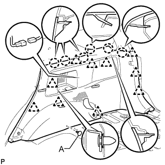
Attach the 10 clips and 6 claws to install the quarter inside trim board.
Install the clip labeled A.
Install the quarter trim hook with the screw.
Connect the rear outer No. 1 seat belt anchor.
Connect the anchor with the bolt.
- Torque:
- 42 N*m{428 kgf*cm, 31 ft.*lbf}
Attach the 2 claws to install the outer lap belt anchor cover.
 |
Connect the rear outer No. 2 seat belt anchor.
Connect the anchor with the bolt.
- Torque:
- 42 N*m{428 kgf*cm, 31 ft.*lbf}
Attach the 2 claws to install the outer lap belt anchor cover.
 |
| 36. INSTALL QUARTER TRIM JACK COVER SUB-ASSEMBLY |
Install the quarter trim jack cover.
| 37. INSTALL QUARTER INSIDE TRIM BOARD RH |
 |
Install the 2 belt hangers to the trim board.
Attach the 10 clips and 6 claws to install the quarter inside trim board.
Install the clip labeled A.
Install the quarter trim hook with the screw.
Connect the rear outer No. 1 seat belt anchor.
Connect the anchor with the bolt.
- Torque:
- 42 N*m{428 kgf*cm, 31 ft.*lbf}
Attach the 2 claws to install the outer lap belt anchor cover.
 |
Connect the rear outer No. 2 seat belt anchor.
Connect the anchor with the bolt.
- Torque:
- 42 N*m{428 kgf*cm, 31 ft.*lbf}
Attach the 2 claws to install the outer lap belt anchor cover.
 |
| 38. INSTALL BACK DOOR SCUFF PLATE |
 |
Attach the 6 clips and 4 claws to install the back door scuff plate.
| 39. INSTALL FRONT PILLAR GARNISH LH |
 |
w/ Curtain Shield Airbag:
Install a new 2 clips on the front pillar garnish.
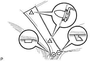
Attach the 2 clips and 2 claws to install the front pillar garnish.
| 40. INSTALL FRONT PILLAR GARNISH RH |
- HINT:
- Use the same procedures described for the LH side.
| 41. INSTALL FRONT ASSIST GRIP SUB-ASSEMBLY |
 |
- HINT:
- Use the same procedures to install the assist grip on the opposite side.
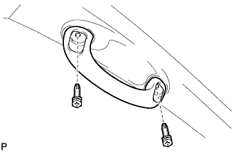
Install the assist grip with the 2 screws.
Attach the 4 claws to install the 2 assist grip plugs.
 |
| 42. INSTALL CENTER PILLAR GARNISH LH |
 |
Attach the claw and clip to install the center pillar garnish.
Connect the front outer seat belt's shoulder anchor.
Connect the shoulder anchor with the bolt.
- Torque:
- 42 N*m{428 kgf*cm, 31 ft.*lbf}
Attach the 4 claws to install the seat belt anchor cover cap.
 |
| 43. INSTALL CENTER PILLAR GARNISH RH |
- HINT:
- Use the same procedures described for the LH side.
| 44. INSTALL LOWER CENTER PILLAR GARNISH LH |
 |
Attach the 2 claws and 2 clips to install the center pillar garnish.
Connect the front outer seat belt anchor's built-in bolt.
Connect the front outer seat belt anchor's built-in bolt.
- Torque:
- 42 N*m{428 kgf*cm, 31 ft.*lbf}
Attach the 2 claws to install the outer lap belt anchor cover.
 |
| 45. INSTALL LOWER CENTER PILLAR GARNISH RH |
- HINT:
- Use the same procedures described for the LH side.
| 46. INSTALL REAR DOOR OPENING TRIM LH |
Install the rear door opening trim weatherstrip.
| 47. INSTALL REAR DOOR OPENING TRIM RH |
Install the rear door opening trim weatherstrip.
| 48. INSTALL REAR DOOR SCUFF PLATE LH |
 |
Attach the 2 clips and 7 claws to install the rear door scuff plate.
| 49. INSTALL REAR DOOR SCUFF PLATE RH |
- HINT:
- Use the same procedures described for the LH side.
| 50. INSTALL COWL SIDE TRIM BOARD LH |
 |
Attach the 2 clips to install the cowl side trim board.
Install the cap nut.
| 51. INSTALL COWL SIDE TRIM BOARD RH |
- HINT:
- Use the same procedures described for the LH side.
| 52. INSTALL FRONT DOOR OPENING TRIM LH |
Install the front door opening trim weatherstrip.
| 53. INSTALL FRONT DOOR OPENING TRIM RH |
Install the front door opening trim weatherstrip.
| 54. INSTALL FRONT DOOR SCUFF PLATE LH |
 |
Attach the 3 clips and 7 claws to install the front door scuff plate.
| 55. INSTALL FRONT DOOR SCUFF PLATE RH |
- HINT:
- Use the same procedures described for the LH side.
| 56. INSTALL REAR NO. 2 SEAT ASSEMBLY LH |
Install the rear No. 2 seat assembly (Toyota Fortuner RM000001DOI002X.html).
| 57. INSTALL REAR NO. 2 SEAT ASSEMBLY RH |
- HINT:
- Use the same procedures described for the LH side.
| 58. CONNECT CABLE TO NEGATIVE BATTERY TERMINAL |
- NOTICE:
- When disconnecting the cable, some systems need to be initialized after the cable is reconnected (Toyota Fortuner RM000002HD2006X.html).
| 59. CHECK SRS WARNING LIGHT |
For vehicles with SRS:
Check SRS warning light (Toyota Fortuner RM000000XFD06DX.html).