INSTALL CENTER INSTRUMENT CLUSTER FINISH PANEL ASSEMBLY (for Automatic Air Conditioning System)
INSTALL AIR CONDITIONING CONTROL ASSEMBLY (for Manual Air Conditioning System)
INSTALL CENTER INSTRUMENT CLUSTER FINISH PANEL ASSEMBLY (for Manual Air Conditioning System)
INSTALL HEATER CONTROL KNOB (for Manual Air Conditioning System)
INSTALL NO. 2 HEATER CONTROL KNOB (for Manual Air Conditioning System)
Upper Instrument Panel -- Installation |
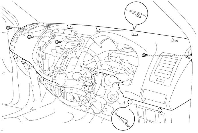
| 1. INSTALL UPPER INSTRUMENT PANEL SUB-ASSEMBLY |
Connect the connectors.
Securely attach the 8 claws to the vehicle body.
Install the instrument panel with the 2 bolts and 2 screws.
| 2. INSTALL FRONT PILLAR GARNISH RH |
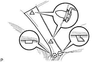 |
w/ Curtain Shield Airbag:
Install a new 2 clips on the front pillar garnish.
Attach the 2 clips and 2 claws to install the front pillar garnish.
| 3. INSTALL FRONT PILLAR GARNISH LH |
- HINT:
- Use the same procedures described for the LH side.
| 4. INSTALL INSTRUMENT PANEL PASSENGER AIRBAG ASSEMBLY |
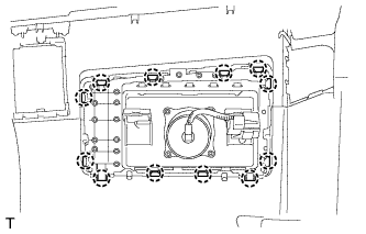 |
Attach the 12 claws to install the airbag.
Attach the clamp to the bracket.
Install the 2 bolts.
- Torque:
- 20 N*m{204 kgf*cm, 15 ft.*lbf}
 |
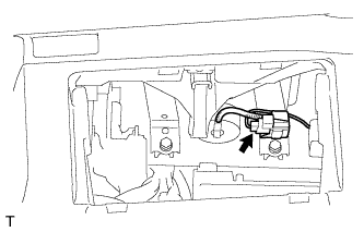
Connect the connector to the airbag.
- NOTICE:
- When handling the airbag connector, do not damage the airbag wire harness.
 |
| 5. INSTALL GLOVE COMPARTMENT DOOR ASSEMBLY |
Attach the 2 hinges to install the door.
 |
While pushing in the sides of the glove compartment door as indicated by the arrows in the illustration, close the door to engage the 2 stoppers.
 |
| 6. INSTALL RADIO RECEIVER ASSEMBLY WITH BRACKET (w/ Audio) |
Install the radio receiver assembly with bracket (Toyota Fortuner RM000003OQ7002X_01_0003.html).
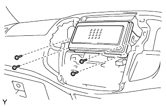
| 7. INSTALL RADIO TUNER OPENING COVER WITH BRACKET (w/o Audio) |
Install the cover with bracket with the 4 screws.
 |
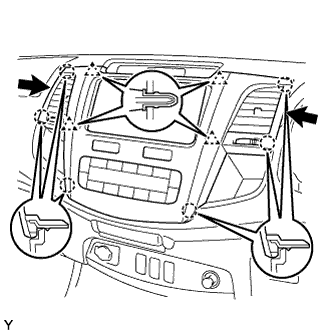
| 8. INSTALL CENTER INSTRUMENT CLUSTER FINISH PANEL ASSEMBLY (for Automatic Air Conditioning System) |
Connect all the connectors.
Attach the 6 claws and 4 clips to install the panel.
 |
| 9. INSTALL AIR CONDITIONING CONTROL ASSEMBLY (for Manual Air Conditioning System) |
Attach the 2 claws to connect the air mix damper control cable.
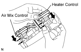 |
Attach the 2 claws to connect the heater control cable.
Connect the connector.
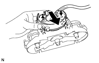 |
Attach the 2 claws to connect the air inlet damper control cable.
Attach the 2 claws to connect the A/C control.
 |
| 10. INSTALL CENTER INSTRUMENT CLUSTER FINISH PANEL ASSEMBLY (for Manual Air Conditioning System) |
Connect all the connectors.
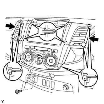 |
Attach the 6 claws and 4 clips to install the panel.
Install the screw.
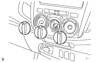
| 11. INSTALL HEATER CONTROL KNOB (for Manual Air Conditioning System) |
Install the control knob.
 |
| 12. INSTALL NO. 2 HEATER CONTROL KNOB (for Manual Air Conditioning System) |
Install the 3 control knobs.
 |
| 13. INSTALL COMBINATION METER ASSEMBLY |
Connect all the connectors.
- NOTICE:
- There are 2 types of combination meters. One type has a 40 pin connector and 16 pin connector. The other type only has a 40 pin connector.
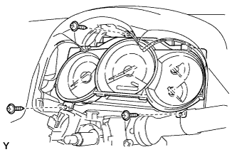 |
Install the combination meter with the 3 screws.
| 14. INSTALL NO. 1 INSTRUMENT CLUSTER FINISH PANEL |
Attach the 2 claws to install the panel.
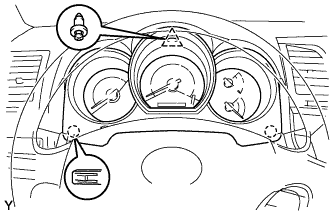 |
Install the clip.
| 15. INSTALL UPPER STEERING COLUMN COVER |
| 16. INSTALL LOWER STEERING COLUMN COVER |
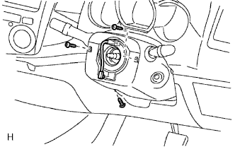 |
Install the lower cover with the 3 screws.
- Torque:
- 2.0 N*m{20 kgf*cm, 18 in.*lbf}
| 17. INSTALL STEERING WHEEL ASSEMBLY |
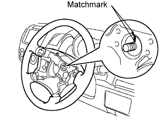 |
Align the matchmarks on the steering wheel and main shaft.
Install the steering set nut.
- Torque:
- 50 N*m{510 kgf*cm, 37 ft.*lbf}
| 18. INSTALL STEERING PAD ASSEMBLY |
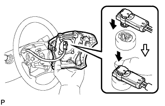 |
Support the steering pad with one hand as shown in the illustration.
Connect the airbag connector.
- NOTICE:
- When handling the airbag connector, do not damage the airbag wire harness.
Connect the horn connector.
Install the steering pad after confirming that the circumference grooves of the screws are caught on the screw case.
Using a T30 "torx" socket, install the 2 screws.
- Torque:
- 8.8 N*m{90 kgf*cm, 78 in.*lbf}
| 19. CONNECT CABLE TO NEGATIVE BATTERY TERMINAL |
- NOTICE:
- When disconnecting the cable, some systems need to be initialized after the cable is reconnected (Toyota Fortuner RM000002HD2006X.html).
| 20. CHECK SRS WARNING LIGHT |
Check the SRS warning light (Toyota Fortuner RM000000XFD06DX.html).