Air Conditioning System (For Automatic Air Conditioning System) Air Conditioning Compressor Magnetic Clutch Circuit
DESCRIPTION
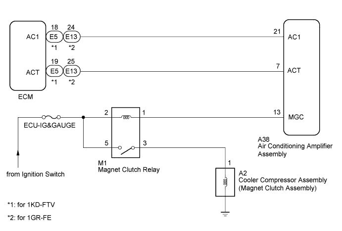
WIRING DIAGRAM
INSPECTION PROCEDURE
READ VALUE USING INTELLIGENT TESTER (A/C SIGNAL)
INSPECT MAGNET CLUTCH RELAY
CHECK HARNESS AND CONNECTOR (AIR CONDITIONING AMPLIFIER - BATTERY)
CHECK AIR CONDITIONING AMPLIFIER ASSEMBLY
INSPECT COOLER COMPRESSOR ASSEMBLY (MAGNET CLUTCH ASSEMBLY)
CHECK HARNESS AND CONNECTOR (MAGNET CLUTCH RELAY - COOLER COMPRESSOR ASSEMBLY AND BATTERY)
CHECK HARNESS AND CONNECTOR (AIR CONDITIONING AMPLIFIER - ECM)
CHECK AIR CONDITIONING AMPLIFIER ASSEMBLY
CHECK HARNESS AND CONNECTOR (AIR CONDITIONING AMPLIFIER - ECM)
CHECK AIR CONDITIONING AMPLIFIER ASSEMBLY
AIR CONDITIONING SYSTEM (for Automatic Air Conditioning System) - Air Conditioning Compressor Magnetic Clutch Circuit |
DESCRIPTION
The air conditioning amplifier assembly outputs the magnet clutch on request signal to the ECM. The ECM sends a magnet clutch on permission signal to the air conditioning amplifier assembly. The air conditioning amplifier assembly turn the magnet clutch on based on the signal.
WIRING DIAGRAM
INSPECTION PROCEDURE
- NOTICE:
- Inspect the fuses for circuits related to this system before performing the following inspection procedure.
| 1.READ VALUE USING INTELLIGENT TESTER (A/C SIGNAL) |
Use the Data List to check if the magnet clutch on request signal is functioning properly (Toyota Fortuner RM000003PQ5001X.html).
ECMTester Display
| Measurement Item/Range
| Normal Condition
| Diagnostic Note
|
A/C Signal
| Magnet clutch on request signal / ON or OFF
| ON: A/C switch on
OFF: A/C switch off
| Check this item with the engine idling and the blower switch on (LO level).
|
- OK:
- Display is as specified in normal condition.
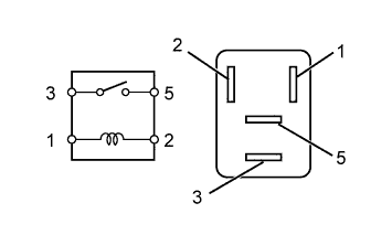
| 2.INSPECT MAGNET CLUTCH RELAY |
Remove the magnet clutch relay.
Measure the resistance according to the value(s) in the table below.
- Standard Resistance:
Tester Connection
| Condition
| Specified Condition
|
3 - 5
| Battery voltage is not applied to terminals 1 and 2
| 10 kΩ or higher
|
Battery voltage is applied to terminals 1 and 2
| Below 1 Ω
|
| | REPLACE MAGNET CLUTCH RELAY |
|
|
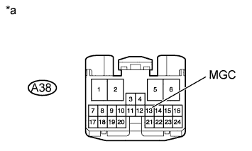
| 3.CHECK HARNESS AND CONNECTOR (AIR CONDITIONING AMPLIFIER - BATTERY) |
Disconnect the A38 air conditioning amplifier assembly connector.
Measure the voltage according to the value(s) in the table below.
- Standard Voltage:
Tester Connection
| Switch Condition
| Specified Condition
|
A38-13 (MGC) - Body ground
| Ignition switch ON
| 11 to 14 V
|
Ignition switch off
| Below 1 V
|
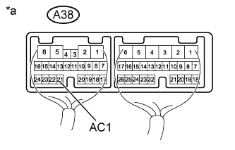
Text in Illustration*a
| Front view of wire harness connector
(to Air Conditioning Amplifier Assembly)
|
| | REPAIR OR REPLACE HARNESS OR CONNECTOR |
|
|
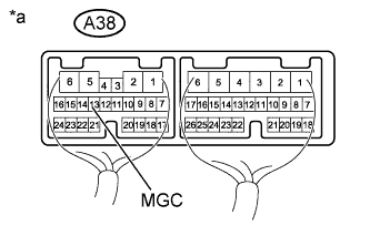
| 4.CHECK AIR CONDITIONING AMPLIFIER ASSEMBLY |
Remove the air conditioning amplifier assembly with its connectors still connected (Toyota Fortuner RM000001K3A018X.html).
Measure the voltage according to the value(s) in the table below.
- Standard Voltage:
Tester Connection
| Condition
| Specified Condition
|
A38-13 (MGC) - Body ground
| - Engine idling
- Blower switch on (LO level)
- A/C switch on (magnet clutch on permitted)
| Below 1 V
|
- Engine idling
- Blower switch on (LO level)
- A/C switch off or on (magnet clutch not on permitted)
| 11 to 14 V
|
Text in Illustration*a
| Component with harness connected
(Air Conditioning Amplifier Assembly)
|
| 5.INSPECT COOLER COMPRESSOR ASSEMBLY (MAGNET CLUTCH ASSEMBLY) |
Remove the cooler compressor assembly.
- for 1KD-FTV: Toyota Fortuner RM0000012JZ028X.html.
- for 1GR-FE: Toyota Fortuner RM0000012JZ026X.html.
Apply battery voltage to the magnet clutch and check operation of the magnet clutch.
- OK:
Measurement Connection
| Specified Condition
|
Battery positive (+) → Terminal 1
Battery negative (-) → Ground wire
| Magnet clutch engages
|
ResultResult
| Proceed to
|
OK
| A
|
NG (for 1KD-FTV)
| B
|
NG (for 1GR-FE)
| C
|
| 6.CHECK HARNESS AND CONNECTOR (MAGNET CLUTCH RELAY - COOLER COMPRESSOR ASSEMBLY AND BATTERY) |
Disconnect the A2 compressor connector.
Remove the magnet clutch relay.
Measure the voltage according to the value(s) in the table below.
- Standard Voltage:
Tester Connection
| Switch Condition
| Specified Condition
|
M1-5 - Body ground
| Ignition switch ON
| 11 to 14 V
|
Ignition switch off
| Below 1 V
|
Measure the resistance according to the value(s) in the table below.
- Standard Resistance:
Tester Connection
| Condition
| Specified Condition
|
M1-3 - A2-1
| Always
| Below 1 Ω
|
| | REPAIR OR REPLACE HARNESS OR CONNECTOR |
|
|
| 7.CHECK HARNESS AND CONNECTOR (AIR CONDITIONING AMPLIFIER - ECM) |
Disconnect the A38 air conditioning amplifier assembly connector.
Disconnect the E5*1 or E13*2 ECM connector.
- *1: for 1KD-FTV
- *2: for 1GR-FE
Measure the resistance according to the value(s) in the table below.
- Standard Resistance:
- for 1KD-FTV:
Tester Connection
| Condition
| Specified Condition
|
A38-7 (ACT) - E5-19 (ACT)
| Always
| Below 1 Ω
|
A38-7 (ACT) - Body ground
| Always
| 10 kΩ or higher
|
- for 1GR-FE:
Tester Connection
| Condition
| Specified Condition
|
A38-7 (ACT) - E13-25 (ACT)
| Always
| Below 1 Ω
|
A38-7 (ACT) - Body ground
| Always
| 10 kΩ or higher
|
| | REPAIR OR REPLACE HARNESS OR CONNECTOR |
|
|
| 8.CHECK AIR CONDITIONING AMPLIFIER ASSEMBLY |
Remove the air conditioning amplifier assembly with its connectors still connected (Toyota Fortuner RM000001K3A018X.html).
Measure the voltage according to the value(s) in the table below.
- Standard Voltage:
Tester Connection
| Condition
| Specified Condition
|
A38-7 (ACT) - Body ground
| - Engine idling
- Blower switch on (LO level)
- A/C switch on (magnet clutch on)
| 11 to 14 V
|
- Engine idling
- Blower switch on (LO level)
- A/C switch off or on (magnet clutch off)
| Below 1 V
|
Text in Illustration*a
| Component with harness connected
(Air Conditioning Amplifier Assembly)
|
ResultResult
| Proceed to
|
OK
| A
|
NG (for 1KD-FTV)
| B
|
NG (for 1GR-FE)
| C
|
| 9.CHECK HARNESS AND CONNECTOR (AIR CONDITIONING AMPLIFIER - ECM) |
Disconnect the A38 air conditioning amplifier assembly connector.
Disconnect the E5*1 or E13*2 ECM connector.
- *1: for 1KD-FTV
- *2: for 1GR-FE
Measure the resistance according to the value(s) in the table below.
- Standard Resistance:
- for 1KD-FTV:
Tester Connection
| Condition
| Specified Condition
|
A38-21 (AC1) - E5-18 (AC1)
| Always
| Below 1 Ω
|
A38-21 (AC1) - Body ground
| Always
| 10 kΩ or higher
|
- for 1GR-FE:
Tester Connection
| Condition
| Specified Condition
|
A38-21 (AC1) - E13-24 (AC1)
| Always
| Below 1 Ω
|
A38-21 (AC1) - Body ground
| Always
| 10 kΩ or higher
|
| | REPAIR OR REPLACE HARNESS OR CONNECTOR |
|
|
| 10.CHECK AIR CONDITIONING AMPLIFIER ASSEMBLY |
Remove the air conditioning amplifier assembly with its connectors still connected (Toyota Fortuner RM000001K3A018X.html).
Measure the voltage according to the value(s) in the table below.
- Standard Voltage:
Tester Connection
| Condition
| Specified Condition
|
A38-21 (AC1) - Body ground
| - Engine idling
- Blower switch on (LO level)
- A/C switch on
| Below 1 V
|
- Engine idling
- Blower switch on (LO level)
- A/C switch off
| 11 to 14 V
|
Text in Illustration*a
| Component with harness connected
(Air Conditioning Amplifier Assembly)
|
ResultResult
| Proceed to
|
NG
| A
|
OK (for 1KD-FTV)
| B
|
OK (for 1GR-FE)
| C
|