Dtc B2286 Runnable Signal Malfunction
DESCRIPTION
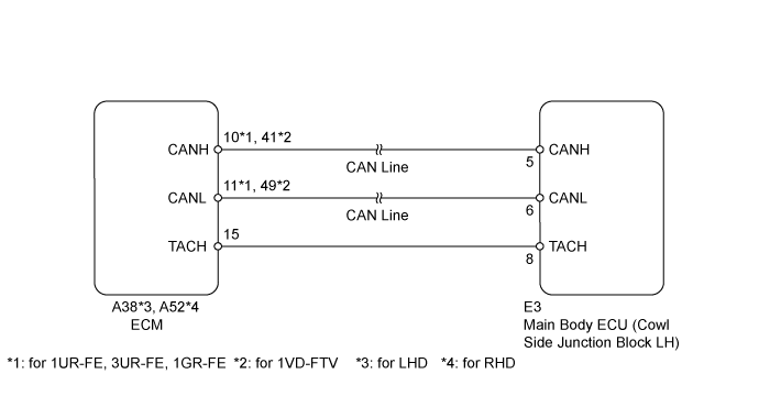
WIRING DIAGRAM
INSPECTION PROCEDURE
READ VALUE USING INTELLIGENT TESTER (ENGINE CONDITION)
CHECK HARNESS AND CONNECTOR (MAIN BODY ECU - ECM)
REPLACE MAIN BODY ECU
DTC B2286 Runnable Signal Malfunction
DESCRIPTION
The main body ECU and ECM are connected by a cable and the CAN communication line. If the cable information and CAN information are inconsistent, this DTC is stored.
| DTC Code | Detection Condition | Trouble Area |
| B2286 | The cable and CAN information between the main body ECU and ECM is inconsistent. | |
WIRING DIAGRAM
INSPECTION PROCEDURE
| 1.READ VALUE USING INTELLIGENT TESTER (ENGINE CONDITION) |
Use the Data List to check if the engine start is functioning properly.
Main Body| Tester Display | Measurement Item/Range | Normal Condition | Diagnostic Note |
| Engine Condition | Engine condition/RUN or STOP | RUN: Engine running
STOP: Engine stopped | - |
Result| Result | Proceed to |
| Display on the intelligent tester does not change according to engine condition | A |
| Display on the intelligent tester changes according to engine condition | B |
| 2.CHECK HARNESS AND CONNECTOR (MAIN BODY ECU - ECM) |
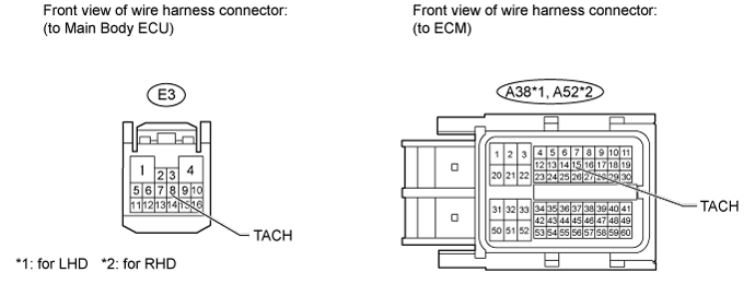
Disconnect the E3 main body ECU connector.
Disconnect the A38 (for LHD) or A52 (for RHD) ECM connector.
Measure the resistance according to the value(s) in the table below.
- Standard Resistance:
| Tester Connection | Condition | Specified Condition |
E3-8 (TACH) - A38-15 (TACH)*1
E3-8 (TACH) - A52-15 (TACH)*2 | Always | Below 1 Ω |
E3-8 (TACH) or A38-15 (TACH) - Body ground*1
E3-8 (TACH) or A52-15 (TACH) - Body ground*2 | Always | 10 kΩ or higher |
| | REPAIR OR REPLACE HARNESS OR CONNECTOR |
|
|
Temporarily replace the main body ECU with a new or normally functioning one.
Check whether DTC B2286 is output.
Result| Result | Proceed to |
| DTC not output | A |
| DTC output (for 1GR-FE) | B |
| DTC output (for 1UR-FE) | C |
| DTC output (for 3UR-FE) | D |
| DTC output (for 1VD-FTV) | E |