Dtc B1501 Sub Fuel Sender Open Detected
DESCRIPTION
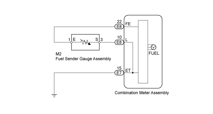
WIRING DIAGRAM
INSPECTION PROCEDURE
READ VALUE USING INTELLIGENT TESTER (FUEL SENDER GAUGE)
CHECK HARNESS AND CONNECTOR (COMBINATION METER - FUEL SENDER GAUGE AND BODY GROUND)
INSPECT FUEL SENDER GAUGE ASSEMBLY
CHECK COMBINATION METER ASSEMBLY
DTC B1501 Sub Fuel Sender Open Detected
DESCRIPTION
- Trouble code B1501 is only output for double tank equipped vehicles
This DTC is stored when the combination meter detects a fuel sender gauge malfunction via the CAN.
| DTC Code | DTC Detection Condition | Trouble Area |
| B1501 | When the combination meter detects a fuel sender gauge malfunction. | Harness or connector
Combination meter assembly
Fuel sender gauge assembly
|
WIRING DIAGRAM
INSPECTION PROCEDURE
| 1.READ VALUE USING INTELLIGENT TESTER (FUEL SENDER GAUGE) |
Combination Meter| Tester Display | Measurement Item/Range | Normal Condition | Diagnostic Note |
| Fuel Input | Fuel sender gauge (main) input signal/Min.: 0, Max.: 127.5 | Fuel sender input value | Unit: L |
Operate the intelligent tester according to the display and select the Data List ().
- OK:
- Fuel value displayed on the intelligent tester is almost same as needle indication.
Result| Result | Proceed to |
| NG | A |
| OK (w/ Multi-information Display) | B |
| OK (w/o Multi-information Display) | C |
| | REPLACE COMBINATION METER ASSEMBLY ()
|
|
|
| | REPLACE COMBINATION METER ASSEMBLY ()
|
|
|
| 2.CHECK HARNESS AND CONNECTOR (COMBINATION METER - FUEL SENDER GAUGE AND BODY GROUND) |
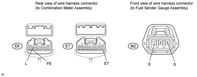
Disconnect the E7 and E8 meter connectors.
Disconnect the M2 gauge connector.
Measure the resistance according to the value(s) in the table below.
- Standard Resistance:
| Tester Connection | Condition | Specified Condition |
| E8-10 (L) - M2-3 (S) | Always | Below 1 Ω |
| E8-22 (FE) - M2-1 (E) |
| E7-15 (ET) - Body ground |
| E8-10 (L) or M2-3 (S) - Body ground | Always | 10 kΩ or higher |
| | REPAIR OR REPLACE HARNESS OR CONNECTOR |
|
|
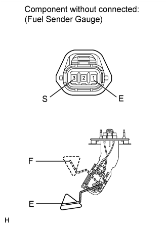
| 3.INSPECT FUEL SENDER GAUGE ASSEMBLY |
for 1GR-FE:
Remove the fuel sender gauge ().
for 1UR-FE:
Remove the fuel sender gauge ().
for 3UR-FE:
Remove the fuel sender gauge ().
for 1VD-FTV:
Remove the fuel sender gauge ().
Measure the resistance according to the value(s) in the table below.
- Standard resistance:
| Tester Connection | Condition | Specified Condition |
| 3 (S) - 1 (E) | Float level is F (upper) | 12 to 18 Ω |
| Float level is E (lower) | 405 to 415 Ω |
Result| Result | Proceed to |
| OK | A |
| NG (for 1GR-FE) | B |
| NG (for 1UR-FE) | C |
| NG (for 3UR-FE) | D |
| NG (for 1VD-FTV) | E |
| | REPLACE FUEL SENDER GAUGE ASSEMBLY ()
|
|
|
| | REPLACE FUEL SENDER GAUGE ASSEMBLY ()
|
|
|
| | REPLACE FUEL SENDER GAUGE ASSEMBLY ()
|
|
|
| | REPLACE FUEL SENDER GAUGE ASSEMBLY ()
|
|
|
| 4.CHECK COMBINATION METER ASSEMBLY |
Check the combination meter type.
Result| Result | Proceed to |
| w/ Multi-information Display | A |
| w/o Multi-information Display | B |
| | REPLACE COMBINATION METER ASSEMBLY ()
|
|
|
| A | |
| |
| REPLACE COMBINATION METER ASSEMBLY ()
|
|