Land Cruiser URJ200 URJ202 GRJ200 VDJ200 - HEATING / AIR CONDITIONING
COMPRESSOR (for 1VD-FTV) - INSTALLATION
| 1. ADJUST COMPRESSOR OIL |
When replacing the compressor and magnetic clutch with a new one, gradually discharge the refrigerant gas from the service valve, and drain the following amount of oil from the new compressor and magnetic clutch before installation.
- Standard:
- VDJ200L-GNMNZV, GNTNZV, GPMNZV:
- (Oil capacity inside the new compressor and magnetic clutch: 140 + 15 cc (4.7 + 0.51 fl.oz.)) - (Remaining oil amount in the removed compressor and magnetic clutch) = (Oil amount to be removed from the new compressor when replacing)
- Except VDJ200L-GNMNZV, GNTNZV, GPMNZV:
- (Oil capacity inside the new compressor and magnetic clutch: 135 + 15 cc (4.6 + 0.51 fl.oz.)) - (Remaining oil amount in the removed compressor and magnetic clutch) = (Oil amount to be removed from the new compressor when replacing)
- NOTICE:
| 2. INSTALL COOLER COMPRESSOR ASSEMBLY |
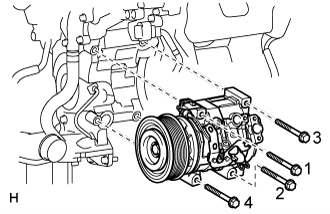
Install the cooler compressor with the 4 bolts.
- Torque:
- 24.5 N*m{ 250 kgf*cm, 18 ft.*lbf}
- HINT:
- Tighten the bolts in the order shown in the illustration.
Connect the connector.
| 3. CONNECT SUCTION HOSE SUB-ASSEMBLY |

Remove the attached vinyl tape from the cooler refrigerant suction hose.
Sufficiently apply compressor oil to a new O-ring and the fitting surface of the cooler compressor.
- Compressor oil:
- ND-OIL 8 or equivalent
Install the O-ring to the suction hose.
Connect the suction hose to the cooler compressor with the bolt.
- Torque:
- 9.8 N*m{ 100 kgf*cm, 87 in.*lbf}
| 4. CONNECT NO. 1 COOLER REFRIGERANT DISCHARGE HOSE |

Remove the attached vinyl tape from the discharge hose.
Sufficiently apply compressor oil to a new O-ring and the fitting surface of the cooler compressor.
- Compressor oil:
- ND-OIL 8 or equivalent
Install the O-ring to the discharge hose.
Connect the discharge hose to the cooler compressor with the bolt.
- Torque:
- 9.8 N*m{ 100 kgf*cm, 87 in.*lbf}
| 5. INSTALL NO. 2 INTAKE AIR CONNECTOR PIPE |

Install the No. 2 intake air connector pipe to the No. 2 inlet compressor elbow.
| *1 | Hose Stopper |
| *a | No Gap |
- NOTICE:
- Make sure there is no gap between the air pipe and hose stopper on the elbow side.
Install the bolt of the No. 2 intake air connector pipe.
- Torque:
- 21 N*m{ 214 kgf*cm, 15 ft.*lbf}
- NOTICE:
- Do not excessively pull the air pipe towards the front of the engine.
Tighten the hose clamp on the elbow side.
- Torque:
- 6.0 N*m{ 61 kgf*cm, 53 in.*lbf}
- HINT:

| *1 | Protrusion |
w/ Intercooler:
Connect the vacuum hose.
| 6. INSTALL NO. 2 AIR CLEANER PIPE SUB-ASSEMBLY |
Connect the No. 2 air cleaner pipe to the No. 2 intake air connector pipe.
Connect the ventilation hose to the oil separator.
Install the pipe with the bolt.
- Torque:
- 21 N*m{ 214 kgf*cm, 15 ft.*lbf}
Tighten the hose clamp.
- Torque:
- 6.3 N*m{ 64 kgf*cm, 56 in.*lbf}
| 7. INSTALL INTERCOOLER ASSEMBLY |
()
| 8. INSTALL RADIATOR ASSEMBLY |
().
| 9. CHARGE REFRIGERANT |
- SST
- 09985-20010(09985-02130,09985-02150,09985-02090,09985-02110,09985-02010,09985-02050,09985-02060,09985-02070)
Perform vacuum purging using a vacuum pump.
Charge refrigerant HFC-134a (R134a).
| Condenser Core Thickness | Air Conditioning Type | Cool Box | Refrigerant Charging Amount |
| 22 mm (0.866 in.) | w/o Rear Cooler | w/ Cool Box | 870 +/-30 g (30.7 +/-1.1 oz.) |
| w/o Cool Box | 870 +/-30 g (30.7 +/-1.1 oz.) | ||
| w/ Rear Cooler | w/ Cool Box | 1010 +/-30 g (35.6 +/-1.1 oz.) | |
| w/o Cool Box | 960 +/-30 g (33.9 +/-1.1 oz.) | ||
| 16 mm (0.630 in.) | w/o Rear Cooler | w/ Cool Box | 770 +/-30 g (27.2 +/-1.1 oz.) |
| w/o Cool Box | 770 +/-30 g (27.2 +/-1.1 oz.) | ||
| w/ Rear Cooler | w/ Cool Box | 970 +/-30 g (34.2 +/-1.1 oz.) | |
| w/o Cool Box | 920 +/-30 g (32.5 +/-1.1 oz.) |

- NOTICE:
| 10. WARM UP ENGINE |
Warm up the engine at less than 1850 rpm for 2 minutes or more after charging the refrigerant.
- NOTICE:
- Be sure to warm up the compressor when turning the A/C switch is on after removing and installing the cooler refrigerant lines (including the compressor), to prevent damage to the compressor.
| 11. CHECK FOR REFRIGERANT GAS LEAK |
After recharging the refrigerant gas, check for refrigerant gas leakage using a halogen leak detector.
Perform the operation under these conditions:
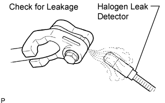
Using a halogen leak detector, check the refrigerant line for leakage.
If a gas leak is not detected on the drain hose, remove the blower motor control (blower resistor) from the cooling unit. Insert the halogen leak detector sensor into the unit and perform the test.
Disconnect the connector and wait for approximately 20 minutes. Bring the halogen leak detector close to the pressure switch and perform the test.