Lighting System - Illumination Circuit
DESCRIPTION
WIRING DIAGRAM
INSPECTION PROCEDURE
PERFORM ACTIVE TEST USING INTELLIGENT TESTER
INSPECT FUSE (DOME2)
CHECK VEHICLE TYPE
CHECK HARNESS AND CONNECTOR (DOME LIGHT - MAP LIGHT AND BODY GROUND)
CHECK HARNESS AND CONNECTOR (MAP LIGHT - BODY GROUND)
INSPECT MAP LIGHT
CHECK HARNESS AND CONNECTOR (NO. 3 ROOM LIGHT - MAP LIGHT AND BODY GROUND)
CHECK VEHICLE TYPE
CHECK HARNESS AND CONNECTOR (SPOT LIGHT - MAP LIGHT AND BODY GROUND)
CHECK HARNESS AND CONNECTOR (NO. 1 ROOM LIGHT - MAP LIGHT AND BODY GROUND)
LIGHTING SYSTEM - Illumination Circuit
DESCRIPTION
When a door is opened while the DOOR switch of the map light assembly is on, the map light assembly receives a door open signal from the main body ECU and turns on the corresponding lights.
WIRING DIAGRAM

INSPECTION PROCEDURE
| 1.PERFORM ACTIVE TEST USING INTELLIGENT TESTER |
Operate the intelligent tester according to the steps on the display and select "Active Test".
Main Body| Tester Display | Test Part | Control Range | Diagnostic Note |
| Illuminated Entry System |
Illumination light | OFF or ON | - |
| OK | |
| |
| PROCEED TO NEXT CIRCUIT INSPECTION SHOWN IN PROBLEM SYMPTOMS TABLE ()
|
|
Remove the DOME2 fuse from the engine room junction block.
Measure the resistance according to the value(s) in the table below.
- Standard Resistance:
| Tester Connection | Condition | Specified Condition |
| DOME2 fuse | Always | Below 1 Ω |
Check the vehicle type.
Result| Result | Proceed to |
| w/o Map Light | A |
| w/ Map Light | B |
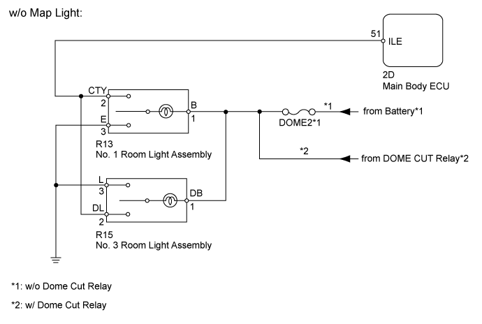
| 4.CHECK HARNESS AND CONNECTOR (DOME LIGHT - MAP LIGHT AND BODY GROUND) |
Disconnect the 2D ECU connector.
Disconnect the R13 light connector.

Measure the resistance according to the value(s) in the table below.
- Standard Resistance:
| Tester Connection | Condition | Specified Condition |
| 2D-51 (ILE) - R13-2 (CTY) | Always | Below 1 Ω |
| R13-1 (B) - Body ground |
| R13-3 (E) - Body ground |
| 2D-51 (ILE) - Body ground | Always | 10 kΩ or higher |
Disconnect the R15 light connector.

Measure the resistance according to the value(s) in the table below.
- Standard Resistance:
| Tester Connection | Condition | Specified Condition |
| 2D-51 (ILE) - R15-2 (DL) | Always | Below 1 Ω |
| R15-1 (DB) - Body ground |
| R15-3 (L) - Body ground |
| 2D-51 (ILE) - Body ground | Always | 10 kΩ or higher |
| | REPAIR OR REPLACE HARNESS AND CONNECTOR |
|
|
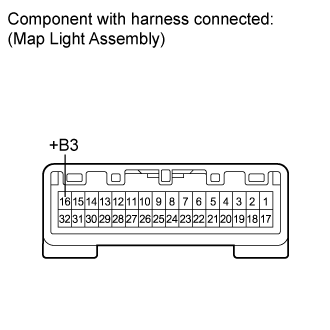
| 5.CHECK HARNESS AND CONNECTOR (MAP LIGHT - BODY GROUND) |
Disconnect the 2D ECU connector.
Measure the voltage according to the value(s) in the table below.
- Standard Voltage:
| Tester Connection | Condition | Specified Condition |
| R7-16 (+B3) - Body ground | Always | 11 to 14 V |
| | REPAIR OR REPLACE HARNESS AND CONNECTOR |
|
|
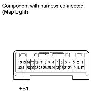
Measure the voltage according to the value(s) in the table below.
- Standard Voltage:
| Tester Connection | Switch Condition | Specified Condition |
| R7-31 (+B1) - R7-5 (RRVT) | Dome light switch off | Below 1 V |
| Dome light switch on | 11 to 14 V |
| R7-6 (RILL) - R7-32 (ILLB) | Dome light switch off | Below 1 V |
| Dome light switch on | 11 to 14 V |
Measure the resistance according to the value(s) in the table below.
- Standard Resistance:
| Tester Connection | Switch Condition | Specified Condition |
| R7-9 (CTY) - Body ground | "Door" switch on and door open | Below 1 Ω |
| "Door" switch off and door open | 10 kΩ or higher |
| "Door" switch on and door closed | 10 kΩ or higher |
| "Door" switch off and door closed | 10 kΩ or higher |
| R7-17 (GND9) - Body ground | Always | Below 1 Ω |
| 7.CHECK HARNESS AND CONNECTOR (NO. 3 ROOM LIGHT - MAP LIGHT AND BODY GROUND) |
Disconnect the R7 map light connector.
Disconnect the R6 light connector.
Measure the resistance according to the value(s) in the table below.
- Standard Resistance:
| Tester Connection | Condition | Specified Condition |
| R7-31 (+B1) - R6-1 (DB) | Always | Below 1 Ω |
| R7-5 (RRVT) - R6-3 (DL) |
| R6-2 (L) - Body ground |
| R7-31 (+B1) - Body ground | Always | 10 kΩ or higher |
| R7-16 (RRVT) - Body ground |
| | REPAIR OR REPLACE HARNESS AND CONNECTOR |
|
|
Check the vehicle type.
Result| Result | Proceed to |
| w/ Sliding Roof | A |
| w/o Sliding Roof | B |
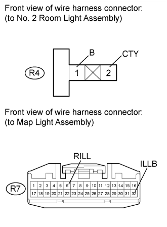
| 9.CHECK HARNESS AND CONNECTOR (SPOT LIGHT - MAP LIGHT AND BODY GROUND) |
Disconnect the R7 map light connector.
Disconnect the R4 light connector.
Measure the resistance according to the value(s) in the table below.
- Standard Resistance:
| Tester Connection | Condition | Specified Condition |
| R7-32 (ILLB) - R4-1 (B) | Always | Below 1 Ω |
| R7-6 (RILL) - R4-2 (CTY) |
| R7-32 (ILLB) - Body ground | Always | 10 kΩ or higher |
| R7-6 (RILL) - Body ground |
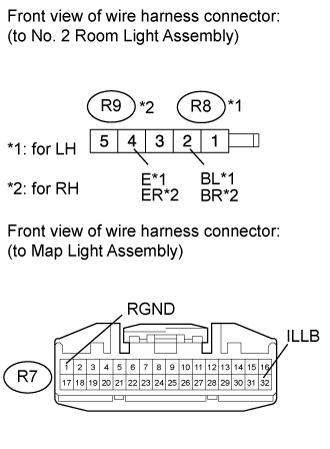
for LH:
Disconnect the R8 light connector.
Measure the resistance according to the value(s) in the table below.
- Standard Resistance:
| Tester Connection | Condition | Specified Condition |
| R7-32 (ILLB) - R8-2 (BL) | Always | Below 1 Ω |
| R7-1 (RGND) - R8-4 (E) |
| R7-32 (ILLB) - Body ground | Always | 10 kΩ or higher |
| R7-1 (RGND) - Body ground |
for RH:
Disconnect the R9 light connector.
Measure the resistance according to the value(s) in the table below.
- Standard Resistance:
| Tester Connection | Condition | Specified Condition |
| R7-32 (ILLB) - R9-2 (BR) | Always | Below 1 Ω |
| R7-1 (RGND) - R9-4 (ER) |
| R7-32 (ILLB) - Body ground | Always | 10 kΩ or higher |
| R7-1 (RGND) - Body ground |
| | REPAIR OR REPLACE HARNESS AND CONNECTOR |
|
|
| 10.CHECK HARNESS AND CONNECTOR (NO. 1 ROOM LIGHT - MAP LIGHT AND BODY GROUND) |
Disconnect the R7 map light connector.
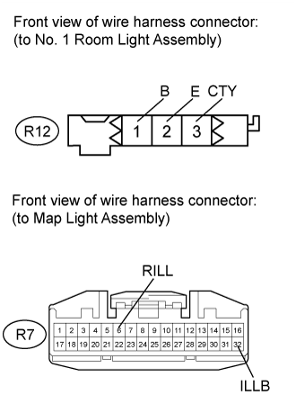
Disconnect the R12 light connector.
Measure the resistance according to the value(s) in the table below.
- Standard Resistance:
| Tester Connection | Condition | Specified Condition |
| R7-32 (ILLB) - R12-1 (B) | Always | Below 1 Ω |
| R7-6 (RILL) - R12-3 (CTY) |
| R12-2 (E) - R7-1 (RGND) |
| R7-32 (ILLB) - Body ground | Always | 10 kΩ or higher |
| R7-6 (RILL) - Body ground |
| | REPAIR OR REPLACE HARNESS AND CONNECTOR |
|
|