Dtc C15C7/78 Dc Motor Power Source Voltage Malfunction
DESCRIPTION
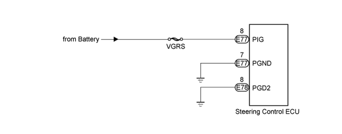
WIRING DIAGRAM
INSPECTION PROCEDURE
CHECK HARNESS AND CONNECTOR (POWER SOURCE CIRCUIT)
RECONFIRM DTC OUTPUT
DTC C15C7/78 DC Motor Power Source Voltage Malfunction
DTC C15C8/79 Power Supply Relay Failure
DESCRIPTION
The steering control ECU monitors PIG (motor power source voltage) and detects a malfunction in the power supply relay (located inside the steering control ECU).
If the steering control ECU detects a malfunction, it will turn on the master warning light, store these DTCs, and stop VGRS operation.
| DTC Code | DTC Detection Condition | Trouble Area |
| C15C7/78 | The steering control ECU detects that the IG terminal voltage is between 9 and 16 V, and the PIG terminal voltage is below 7 V or higher than 18.5 V for 2.4 seconds. | Harness or connector
Steering control ECU
|
| C15C8/79 | The steering control ECU detects a malfunction in the power source relay or an open circuit. | Harness or connector
Steering control ECU
|
WIRING DIAGRAM
INSPECTION PROCEDURE
- The fault may be intermittent. Check the harnesses and connectors thoroughly and retest.
| 1.CHECK HARNESS AND CONNECTOR (POWER SOURCE CIRCUIT) |
Record and clear the DTCs ().
Measure the resistance and voltage according to the value(s) in the table below.
- Standard Resistance:
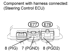
| Tester Connection | Condition | Specified Condition |
| E77-7 (PGND) - Body ground | Always | Below 1 Ω |
| E78-8 (PGD2) - Body ground |
- Standard Voltage:
| Tester Connection | Condition | Specified Condition |
| E77-8 (PIG) - Body ground | Always | 11 to 14 V |
| | REPAIR OR REPLACE HARNESS OR CONNECTOR |
|
|
Check for DTCs ().
Result| Result | Proceed to |
| C15C7/78 or C15C8/79 is not output | A |
| C15C7/78 or C15C8/79 is output (for LHD) | B |
| C15C7/78 or C15C8/79 is output (for RHD) | C |
| | REPLACE STEERING CONTROL ECU ()
|
|
|
| | REPLACE STEERING CONTROL ECU ()
|
|
|
| A | |
| |
| USE SIMULATION METHOD TO CHECK ()
|
|