Land Cruiser URJ200 URJ202 GRJ200 VDJ200 - 1UR-FE ENGINE CONTROL
THROTTLE BODY - INSTALLATION
| 1. INSTALL THROTTLE BODY WITH MOTOR ASSEMBLY |

Install the No. 4 water by-pass hose to the throttle body with motor assembly.
| *1 | Paint Mark |
- HINT:
- When installing the hose, make sure the paint mark and clip are as shown in the illustration.
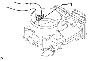
Install the No. 12 water by-pass hose to the throttle body with motor assembly.
| *1 | Paint Mark |
- HINT:
- When installing the hose, make sure the paint mark and clip are as shown in the illustration.
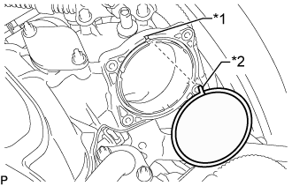
Align the protrusion of a new gasket with the groove of the intake manifold and install the gasket to the intake manifold.
| *1 | Groove |
| *2 | Protrusion |
Install the throttle body with motor assembly with the 4 bolts.
- Torque:
- 10 N*m{ 102 kgf*cm, 7 ft.*lbf}
Connect the throttle position sensor and control motor connector.
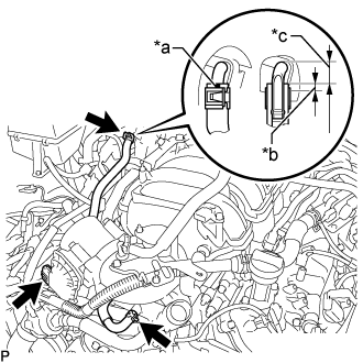
Connect the No. 4 water by-pass hose and No. 12 water by-pass hose.
| *a | Paint Mark |
| *b | 5 mm (0.197 in.) |
| *c | 13 to 17 mm (0.511 to 0.669 in.) |
- HINT:
- When connecting the No. 12 water by-pass hose, make sure the paint marks and clips are as shown in the illustration.
| 2. INSTALL AIR CLEANER CAP AND HOSE |
Install the air cleaner cap and hose, and then tighten the hose clamp.
- Torque:
- 2.5 N*m{ 25 kgf*cm, 22 in.*lbf}
Attach the 4 clamps.
Connect the mass air flow meter connector and attach the clamp.
Connect the No. 2 PCV hose and No. 1 air hose.
| 3. ADD ENGINE COOLANT |
Add engine coolant.
- Standard Capacity (w/o ATF Warmer):
Item Specified Condition w/ Rear Heater 16.5 liters (17.4 US qts, 14.5 Imp. qts) w/o Rear Heater 13.8 liters (14.6 US qts, 12.1 Imp. qts)
- Standard Capacity (w/ ATF Warmer):
Item Specified Condition w/ Rear Heater 17.0 liters (18.0 US qts, 15.0 Imp. qts) w/o Rear Heater 14.2 liters (15.0 US qts, 12.5 Imp. qts)
- NOTICE:
- Do not substitute plain water for engine coolant.
- HINT:
Slowly pour coolant into the radiator reservoir until it reaches the F line.
Install the reservoir cap.
Install the radiator cap.*1
Start the engine and stop it immediately.*2
Allow approximately 10 seconds to pass. Then remove the radiator cap and check the coolant level. If the coolant level has decreased, add coolant.*3
Repeat steps *1, *2 and *3 until the coolant level does not decrease.
- HINT:
- Be sure to perform this step while the engine is cold, as air in the No. 1 radiator hose will flow into the radiator if the engine is warmed up and the thermostat opens.
Install the radiator cap.*4
Set the air conditioning as follows.*5
| Item | Condition |
| Fan speed | Any setting except off |
| Temperature | Toward WARM |
| Air conditioning switch | Off |
Start the engine, warm it up until the thermostat opens, and then continue to run the engine for several minutes to circulate the coolant.*6
- CAUTION:
- NOTICE:
- HINT:
Stop the engine, wait until the engine coolant cools down to ambient temperature. Then remove the radiator cap and check the coolant level.*7
- CAUTION:
- Do not remove the radiator cap while the engine and radiator are still hot. Pressurized, hot engine coolant and steam may be released and cause serious burns.
If the coolant level has decreased, add coolant and warm up the engine until the thermostat opens.*8
If the coolant level has not decreased, check that the coolant level in the radiator reservoir is at the F line.
If the coolant level is below the F line, repeat steps *4 through *8.
If the coolant level is above the F line, drain coolant until the coolant level reaches the F line.
| 4. INSPECT FOR COOLANT LEAK |
- CAUTION:
- To avoid being burned, do not remove the radiator reservoir cap while the engine and radiator are still hot. Thermal expansion may cause hot engine coolant and steam to blow out from the radiator.
Remove the radiator cap.
Check for excessive deposits of rust or scales around the radiator reservoir cap and radiator reservoir filler hole. Also, the engine coolant should be free of oil.
If excessively dirty, replace the engine coolant.
Install the radiator cap.
| 5. INSTALL NO. 1 ENGINE UNDER COVER SUB-ASSEMBLY |
Install the No. 1 engine under cover sub-assembly with the 10 bolts.
- Torque:
- 29 N*m{ 296 kgf*cm, 21 ft.*lbf}
| 6. INSTALL FRONT FENDER SPLASH SHIELD SUB-ASSEMBLY RH |
Push in the clip to install the front fender splash shield sub-assembly RH.
Install the 3 bolts and 2 screws.
| 7. INSTALL FRONT FENDER SPLASH SHIELD SUB-ASSEMBLY LH |
Push in the clip to install the front fender splash shield sub-assembly LH.
Install the 3 bolts and screw.
| 8. INSTALL V-BANK COVER SUB-ASSEMBLY |
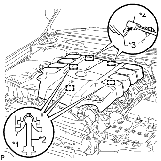
Attach the 2 V-bank cover hooks to the bracket. Then align the 3 V-bank cover grommets with the 3 pins, and press down on the V-bank cover to attach the pins.
| *1 | Grommet |
| *2 | Pin |
| *3 | Hook |
| *4 | Bracket |
| 9. PERFORM INITIALIZATION |
- NOTICE:
Disconnect the EFI fuse, wait at least 60 seconds, and then reconnect the fuse.
Turn the engine switch on (IG) without operating the accelerator pedal.
- NOTICE:
- If the accelerator pedal is operated, perform the above steps again.
Connect the GTS to the DLC3 and clear the DTCs ().
Start the engine and check that the MIL is not illuminated and that the idle speed is within the specified range when the A/C is switched off after the engine is warmed up.
- Standard:
Condition Engine Idle Speed A/C switched off 650 to 750 rpm
- NOTICE:
Enter the following menus: Powertrain / Engine and ETC / Data List / Throttle Sensor Volt %. Fully depress the accelerator pedal and check that the value is 60% or more.
Perform a road test and confirm that there are no abnormalities.