Land Cruiser URJ200 URJ202 GRJ200 VDJ200 - 3UR-FE ENGINE CONTROL
RELAY - ON-VEHICLE INSPECTION
| 1. INSPECT INTEGRATION RELAY (IG2) |
Measure the resistance of the IG2 MAIN fuse.
Remove the IG2 MAIN fuse from the integration relay.
Measure the resistance according to the value(s) in the table below.
- Standard Resistance:
Tester Connection Condition Specified Condition IG2 MAIN fuse Always Below 1 Ω
If the result is not as specified, replace the IG2 MAIN fuse.
Install the IG2 MAIN fuse to the integration relay.

Measure the resistance of the ignition relay No. 2 (IG2) circuit.
Measure the resistance according to the value(s) in the table below.
- Standard Resistance:
Tester Connection Condition Specified Condition 1C-1 - 1B-8 Battery voltage is not applied to terminals 1B-6 and 1B-7 10 kΩ or higher Battery voltage is applied to terminals 1B-6 and 1B-7 Below 1 Ω
| *a | Component without harness connected (Integration Relay) |
If the result is not as specified, replace the integration relay.
| 2. INSPECT INTEGRATION RELAY (EFI) |
Measure the resistance of the EFI MAIN fuse.
Remove the EFI MAIN fuse from the integration relay
Measure the resistance according to the value(s) in the table below.
- Standard Resistance:
Tester Connection Condition Specified Condition EFI MAIN fuse Always Below 1 Ω
If the result is not as specified, replace the EFI MAIN fuse.
Install the EFI MAIN fuse to the integration relay.
Measure the resistance of the EFI relay circuit.
Measure the resistance according to the value(s) in the table below.
- Standard Resistance:
Tester Connection Condition Specified Condition 1C-1 - 1B-4 Battery voltage is not applied to terminals 1B-2 and 1B-3 10 kΩ or higher Battery voltage is applied to terminals 1B-2 and 1B-3 Below 1 Ω
| *a | Component without harness connected (Integration Relay) |
If the result is not as specified, replace the integration relay.
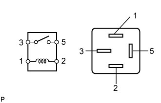
| 3. INSPECT EFI NO. 2 RELAY |

Measure the resistance according to the value(s) in the table below.
- Standard Resistance:
Tester Connection Condition Specified Condition 3 - 5 Battery voltage is not applied to terminals 1 and 2 10 kΩ or higher Battery voltage is applied to terminals 1 and 2 Below 1 Ω
If the result is not as specified, replace the relay.
| 4. INSPECT INTEGRATION RELAY (A/F) |
Measure the resistance of the A/F fuse.
Remove the A/F fuse from the integration relay.
Measure the resistance according to the value(s) in the table below.
- Standard Resistance:
Tester Connection Condition Specified Condition A/F fuse Always Below 1 Ω
If the result is not as specified, replace the A/F fuse.
Install the A/F fuse to the integration relay.

Measure the resistance of the A/F sensor heater relay circuit.
Measure the resistance according to the value(s) in the table below.
- Standard Resistance:
Tester Connection Condition Specified Condition 1C-1 - 1A-4 Battery voltage is not applied to terminals 1A-2 and 1A-3 10 kΩ or higher Battery voltage is applied to terminals 1 A-2 and 1A-3 Below 1 Ω
| *a | Component without harness connected (Integration Relay) |
If the result is not as specified, replace the integration relay.
| 5. INSPECT MAIN BODY ECU (IG1 NO. 1) |
Measure the resistance according to the value(s) in the table below.

| *a | Component without harness connected (Main Body ECU) | - | - |
- Standard Resistance:
Tester Connection Condition Specified Condition 2A-1 - 2B-17 Battery voltage is not applied to terminals 2B-5 and 2D-43 10 kΩ or higher Battery voltage is applied to terminals 2B-5 and 2D-43 Below 1 Ω
If the result is not as specified, replace the main body ECU.
| 6. INSPECT STARTER RELAY (ST) |
Measure the resistance according to the value(s) in the table below.
- Standard Resistance:
Tester Connection Condition Specified Condition 3 - 5 Battery voltage not applied to terminals 1 and 2 10 kΩ or higher Battery voltage applied to terminals 1 and 2 Below 1 Ω
If the result is not as specified, replace the starter relay.
| 7. INSPECT STARTER CUT RELAY (ST CUT) |
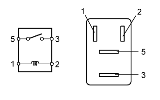
Measure the resistance according to the value(s) in the table below.
- Standard Resistance:
Tester Connection Condition Specified Condition 3 - 5 Battery voltage not applied to terminals 1 and 2 10 kΩ or higher Battery voltage applied to terminals 1 and 2 Below 1 Ω
If the result is not as specified, replace the starter relay.
| 8. INSPECT MAIN BODY ECU (ACC RELAY) |
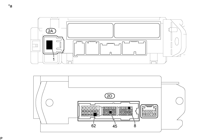
| *a | Component without harness connected (Main Body ECU) | - | - |
Measure the resistance of the ACC relay circuit.
Measure the resistance according to the value(s) in the table below.
- Standard Resistance:
Tester Connection Condition Specified Condition 2A-1 - 2D-8 Battery voltage not applied between 2D-45 and 2D-62 10 kΩ or higher Battery voltage applied between 2D-45 and 2D-62 Below 1 Ω
If the result is not as specified, replace the main body ECU.